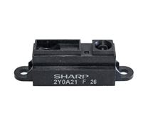
IR DISTANCE SENSING MODULE 45CM
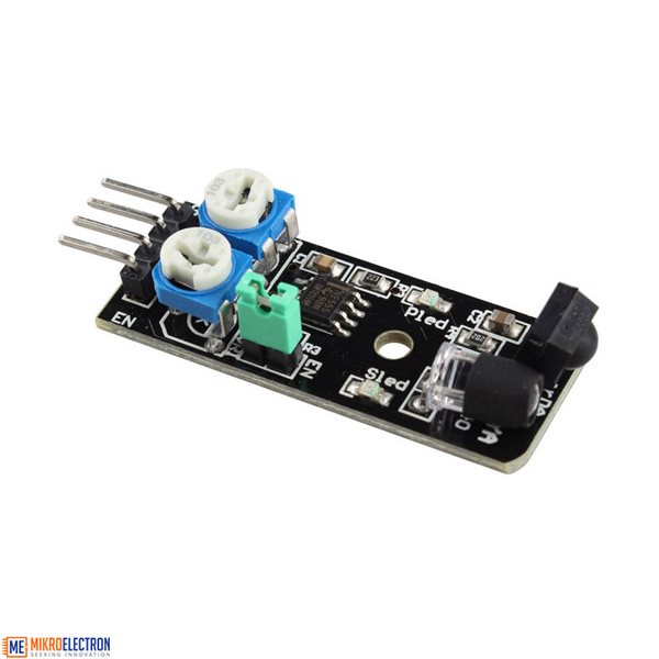
Description:
Allows for sensing of solid objects is sensed output 0, output 1 is not sensitive to the time, directly with 3V and 5V microcontroller IO port connected.
Sensing distance 2-40 cm, distance, good anti-jamming capability. (Note: The infrared sensor can not detect all objects get the same distance, objects of different colors of light reflectance of different objects closer darker black shorter distance detected, the sensor 2-40 cm is measured against the white wall of)
Speed, suitable for smart car obstacle avoidance, black and white line tracking, anti-drop, product counters, cutting lines, liquid level detection.
This sensor is made with black and white lines tracing the car ran without black line on white paper, available in concrete The yellow complex environment such as the black line patrol track. As long as the black line around the slightly lighter color than black can, eliminating the traditional moves, so that environmental layout easier.
The sensor 3 to 6V supply, wide range, suitable for 3V and 5V MCU system.
With Enable, EN terminal is equal to "1" when the sensor does not work, equal to "0" when working. Jump on the sensor end cap long after the EN grounding plug (EN long as "0"). To use the EN pin when the jumper cap is removed.
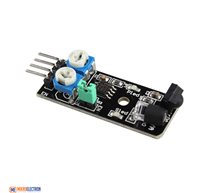
Frequency adjustment potentiometer is used to adjust the carrier frequency of the infrared emission tube, because the integration receiver 38KHZ in particular when the carrier frequency is the most sensitive. The 502 resistor clockwise transferred do (that is, the launch tube at maximum brightness), and then at a white wall tone 103 resistance, has been transferred to the sensing distance is the farthest so far so that the sensor will work in the best state
thin a fixed range (adjustable with on-board potentiometer). Ideal for robotic applications. Depending on the position of the potentiometers and the reflective surface type the sensing range is between 5 to 45cm (approx.).
Module Adjustments
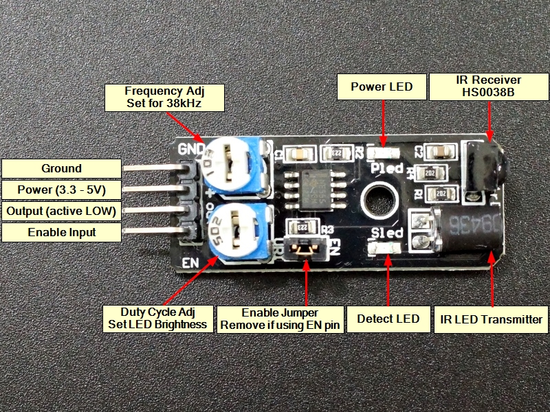
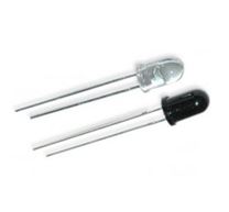
The module includes a 555 timer that is used to drive the IR LED. There are two single-turn potentiometers for adjusting the frequency and duty cycle of the 555 timer.
Frequency Adjust:
The module operates at 38 kHz as the HS0038B receiver module is designed to specifically look for IR pulsing at a 38 kHz rate. The potentiometer next to the GND pin is used to adjust the frequency of the 555 timer and is set to approximately 38 kHz from the factory and shouldn’t be readjusted unless you have a scope or frequency counter to calibrate the frequency. We have noted that some modules function best at a higher frequency up around 41kHz.
Duty Cycle Adjust:
The other potentiometer allows for adjustment of the duty cycle of the 555 timer. This affects the brightness of the IR LED and it can be fiddled with to try to change the distance at which objects are detected.
If this potentiometer is adjusted too far CW, the module may show that it is always detecting an obstacle even when it isn’t. In this case, adjust the potentiometer CCW until the LED goes off when there is no obstacle in front of the sensor.
- GND = Ground. Must be common with the MCU ground.
- + = Power (3.3 – 5V)
- OUT = Output, normally HIGH. Output is pulsed LOW when an obstacle is detected.
- EN = Enable, active HIGH. When the on-board jumper is installed, EN is pulled to Vcc and always enabled. If jumper is removed, an output pin from a MCU can be used to enable the device.
Features:
- Working voltage: DC 3.3V - 5V
- Working current: 20mAh
- Working temperature: -10'C ~ +50'C
- Detection distance: 2 ~ 40cm
- IO interface: 4 line (-/+/S/EN)
- Output signal: TTL Level
- Adjusting mode: Multi resistance regulation
- Effective angle: 35°
- Size: 4.5 * 1.1cm(approx)
- Here we use the obstacle avoidance module and digital 13 interface with LED to build a simple circuit, making the obstacle avoidance warning light, accessing the avoidance sensor to digital 3 interface, when the obstacle avoidance sensor senses the signal, LED light, otherwise off.
IR Infrared Obstacle Avoidance Sensor Features:
- Easy to assemble and use
- Onboard detection indication
- Effective distance range of 2cm to 40cm
- Preset knob to fine tune distance range
Documents:
1 x Obstacle avoidance sensor
Mikroelectron Code:
/*
Exercise IR Obstacle Avoidance Sensor
Basic code to implement obstacle detection using the EN pin to enable the device.
When the EN pin is enabled, it will cause a false detect trigger, so it is necessary to enable
and then delay reading the detection output pin. This also includes a 2nd read to make sure any
detection is valid.
If an obstacle is detected, you would obviously want to implement some type of
avoidance rather than simply loop as we do here.
*/
int LEDPin = 13; // On board LED
int EnablePin = 8; // Arbitrary digital pins that are connected to device.
int OutputPin = 9;
boolean objectDetect = false;
//===============================================================================
// Initialization
//===============================================================================
void setup() {
pinMode(LEDPin, OUTPUT); // LED
pinMode (EnablePin, OUTPUT); // Enable Pin of the device
pinMode (OutputPin, INPUT); // Output Pin of the device
Serial.begin(9600);
}
//===============================================================================
// Main
//===============================================================================
void loop() {
digitalWrite( EnablePin, HIGH); // Enable the internal 38kHz signal from the 555 timer.
delay(1); // Wait 1mSec for signal to stabilize
if( digitalRead( OutputPin)) // If detector Output is HIGH,
{
objectDetect = false; // then no object was detected;
}
else // If the Output is LOW,
{
delay(1); // wait for another 1mSec and check again
if( digitalRead(OutputPin)) // If the Output is now HIGH,
{ // then first Read was noise
objectDetect = false; // and no object was detected, so ignore
}
else // else if the Output is still LOW,
{
objectDetect = true; // then a valid object was detected.
digitalWrite (LEDPin, HIGH); // turn on LED to show the detection.
Serial.println("Object Detected"); // Also send detection to the serial monitor window
delay(500);
digitalWrite (LEDPin, LOW); // turn LED back off
}
}
digitalWrite( EnablePin, LOW); // Disable the internal 38kHz signal.
delay(1000); // wait for 1 Sec or some other arbitrary time period
//and then do again.
}
Related Products
subscribe to our weekly newsletter
We are an online electronics store based in Jordan-Amman. The products we sell ranges from electronic products to modules and much more.
- AMMAN, Jordan. University Street, Khalifa Building 3rd floor
- Mobile: +962 7900 621 96, +962 65344772, +9627 8877 5522
- Phone: +962 6 5344772
- Fax: +96265344778
- Email: info@mikroelectron.com

2024 © Mikroelectron. ALL Rights Reserved. | Distributor Area
Made With By Tashfier.