KY-035 Analog Hall Effect Magnetic Sensor Module
Description:
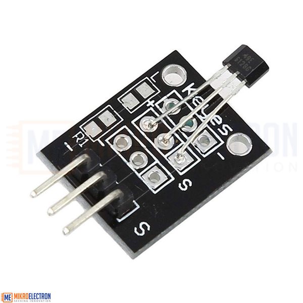
The Analog Hall Effect Sensor Module uses the 49E sensor to detect North and South pole and relative strength of a magnetic field.
Hall Effect sensors detect the presence of a magnetic field and are commonly used for measuring the RPM of rotating assemblies where a magnet on the assembly alternately makes and breaks magnetic contact with the sensor as the assembly rotates. They can even be used to detect electrical current flow through conductors in some cases.
This sensor utilizes an analog 49E sensor. With no magnetic field present, the sensor output rests at approximately 50% of Vcc. In the case of 5V power, the output will be about 2.5V when at rest. When a magnetic field comes near, the voltage will rise or fall depending on whether the south or north pole of the magnet is coming near. If a south pole of a magnet is placed near the front of the sensor (side with the labeling), the output voltage will linearly ramp up towards Vcc to a maximum of 4.2V. If the north pole of the magnet is presented, the voltage will linearly ramp down towards ground to a minimum of 0.86V. The amount of the voltage rise or fall will depend on the magnetic strength of the field.
To use this analog sensor with a microcontroller, it should be hooked up to an analog input. The output will read approximately 1/2 Vcc with no magnetic field present. When a magnetic field approaches, the voltage will change linearly at a rate of 2.5mV / G. Gauss (G) is the unit of measure for magnetism.
KEY FEATURES OF ANALOG HALL EFFECT MODULE:
Use 49E analog Hall Effect sensor
Can differentiate between North and South pole of the magnet
Detects the strength of the magnetic field
3.3 or 5V operation
Features:
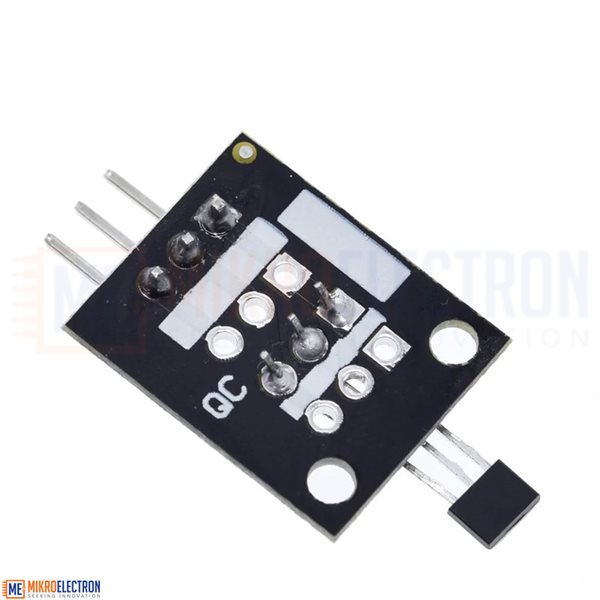
There is a 3-pin header on the assembly. There are a couple of different pin labeling schemes since the same board is used for several modules.
G or ‘-‘ = Ground
R or Center pin = Vcc (3.3 or 5V typical)
Y or S = Analog output, connects to analog input on MCU
|
Operating Ratings |
Vcc Range |
3 – 6.5V |
|
Analog Output (no magnetic field) |
1/2 Vcc |
|
|
Analog Output (Max South pole field) |
4.2V |
|
|
Analog Output (Max North pole field) |
0.86V |
|
|
Sensitivity |
2.5mV / G |
|
|
Dimensions |
L x W (PCB) |
20mm x 15mm (0.8 x 0.6″) |
|
Length including sensor |
25mm (1″) |
Kit include:
1 x Analog Hall Effect Sensor Module
Mikroelectron Code:
/*
Analog Hall Effect module test
Basic code for reading the analog output of the hall effect module.
*/
const int AnalogPin = A0;
const float GAUSS_PER_STEP = 1.96; // Sensor outputs 2.5mV / Gauss.
// ADC step is about 4.89mV / Step
float rawValue = 0.0;
float gaussValue = 0.0;
float zeroLevel = 530.0; // Adjust as needed to get zero output with no magnetic field present.
//===============================================================================
// Initialization
//===============================================================================
void setup()
{
pinMode (AnalogPin, INPUT);
Serial.begin(9600); // Set comm speed for debug window messages
}
//===============================================================================
// Main
//===============================================================================
void loop()
{
rawValue = analogRead (AnalogPin) - zeroLevel; // Output normalized to '0' with no field present
Serial.print ("Reading Raw: ");
Serial.println (rawValue);
// Reading positive relative to the South Pole, the North Pole negative
gaussValue = rawValue * GAUSS_PER_STEP;
Serial.print ("Reading in Gauss: ");
Serial.println (gaussValue);
delay (3000);
}
Related Products


subscribe to our weekly newsletter
We are an online electronics store based in Jordan-Amman. The products we sell ranges from electronic products to modules and much more.
- AMMAN, Jordan. University Street, Khalifa Building 3rd floor
- Mobile: +962 7900 621 96, +962 65344772, +9627 8877 5522
- Phone: +962 6 5344772
- Fax: +96265344778
- Email: info@mikroelectron.com

2024 © Mikroelectron. ALL Rights Reserved. | Distributor Area
Made With By Tashfier.