


CP2102 USB 2.0 to TTL UART Module 6Pin for ARDUINO pro mini
The CP2102 USB 2.0 to TTL UART Module (6-Pin) is a compact, reliable USB-to-Serial converter built around the Silicon Labs CP2102 chip. It allows any computer to communicate with microcontrollers, Arduino Pro Mini boards, ESP8266/ESP32 modules, and 3.3V/5V serial devices through a standard USB port. The module features selectable 3.3V / 5V output, power and TX/RX indicator LEDs, and a 6-pin standard header for direct connection to Arduino Pro Mini. It is the perfect tool for programming, debugging, and firmware flashing.
وحدة CP2102 USB 2.0 إلى UART (6 منافذ) هي محوّل USB إلى تسلسلي صغير الحجم وموثوق، مبني على شريحة Silicon Labs CP2102. يتيح للحاسوب التواصل مع المتحكمات الدقيقة، لوحات Arduino Pro Mini، وحدات ESP8266/ESP32، وأجهزة التسلسلي بجهد 3.3 فولت / 5 فولت عبر منفذ USB قياسي. تتميز الوحدة بـخرج جهد قابل للاختيار 3.3 فولت / 5 فولت، مؤشرات LED للطاقة وخطوط TX/RX، وهيدر قياسي 6 منافذ للتوصيل المباشر بـ Arduino Pro Mini. أداة مثالية لـالبرمجة، التصحيح، وتحديث البرامج الثابتة.
The CP2102 USB to TTL UART Module is one of the most popular and reliable USB-to-Serial bridges used in the maker, embedded, and prototyping communities. Based on the genuine Silicon Labs CP2102 single-chip USB-to-UART bridge controller, the module allows any PC, laptop, or Mac to communicate over a standard USB port with microcontrollers, sensors, GPS modules, GSM modems, and any 3.3V / 5V serial device.
When connected to a computer via the USB port, the module appears as a standard virtual COM (serial) port, fully compatible with the Arduino IDE Serial Monitor, PuTTY, Tera Term, RealTerm, Python pySerial, and any other serial software. Drivers are widely available for Windows, macOS, and Linux directly from the Silicon Labs website.
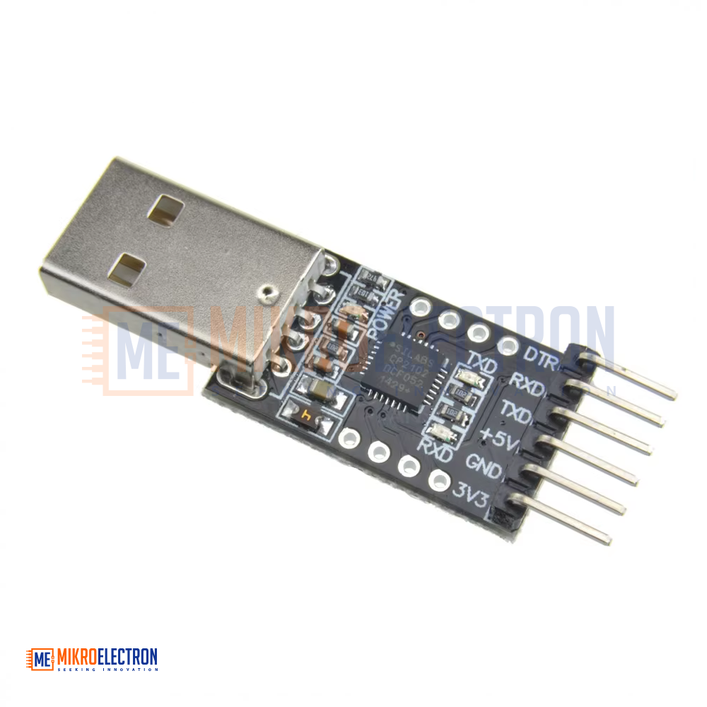
The module is specifically designed with a 6-pin header layout (DTR, RX, TX, VCC, CTS, GND) that matches the FTDI pinout of the Arduino Pro Mini, allowing it to be plugged in directly for uploading sketches. The on-board DTR pin automatically resets the target microcontroller, making the upload process seamless and avoiding the need to press the reset button manually.
A jumper or solder bridge on the back of the board lets the user select between 3.3V and 5V output, which is critical when working with 3.3V devices such as ESP8266, ESP32, nRF24L01, Bluetooth HC-05, and many sensors — feeding them 5V can permanently damage them. Three on-board LEDs (PWR, TXD, RXD) provide instant visual feedback about power state and data activity.
Specifications
- Main Chip: Genuine Silicon Labs CP2102
- Interface: USB 2.0 (Full-Speed)
- Output Logic Level: 3.3V or 5V (selectable)
- Pin Header: 6-pin (DTR, RX, TX, VCC, CTS, GND) — FTDI / Arduino Pro Mini compatible
- Indicator LEDs: PWR (Power), TXD, RXD
- Baud Rate: Up to 1 Mbps
- Supported OS: Windows (XP / 7 / 8 / 10 / 11), macOS, Linux, Android
- USB Connector: Mini-B (or Micro-B, depending on version)
- Power Supply: Powered from USB (no external supply needed)
- PCB Material: FR4 (high-quality double-sided)
- Dimensions: approx. 51.4 × 16.5 × 10 mm
- Weight: 6 g
- Color: Black PCB with high-grade gold-plated headers
- Packaging: Individual anti-static bag
Pinout (6-Pin Header)
| Pin | Function |
|---|---|
| DTR | Data Terminal Ready — used for auto-reset of target MCU |
| RX | Module receive (connect to TX of target device) |
| TX | Module transmit (connect to RX of target device) |
| VCC | 3.3V or 5V output (selectable) |
| CTS | Clear To Send (optional handshake) |
| GND | Ground |
Applications
- Programming Arduino Pro Mini and other bootloaded microcontrollers
- Flashing firmware to ESP8266, ESP32, and ESP-01 modules
- Debugging serial communication with sensors and modules (GPS, GSM, Bluetooth)
- Communicating with microcontrollers (AVR, PIC, STM32, MSP430) via UART
- Updating firmware on 3D printer controllers, drones, RC equipment
- Connecting industrial devices with serial interfaces to a modern PC
- Logging serial data from data-loggers and sensor systems
- Configuring Bluetooth modules (HC-05, HC-06, BT-04)
- Reverse-engineering and hardware-hacking projects
- STEM and embedded-systems education
- AT command testing for GSM, GPS, and Wi-Fi modules
- Bridging legacy RS-232 devices to USB (when paired with a level converter)