


PC817 Optocoupler ICs
The PC817 Optocoupler IC is a compact and reliable component used for electrical isolation between circuits using light. It integrates an infrared LED and a phototransistor in a single package, allowing signals to pass without direct electrical connection. This ensures protection for sensitive components against noise, voltage spikes, and interference. The PC817 is widely used in power supplies, microcontroller interfaces, and industrial control systems. Its simple design and low cost make it ideal for both professional and DIY electronics projects.
دائرة PC817 Optocoupler هي مكون إلكتروني صغير يُستخدم لعزل الدوائر كهربائياً باستخدام الضوء. تحتوي على LED بالأشعة تحت الحمراء وترانزستور ضوئي داخل نفس الشريحة، مما يسمح بنقل الإشارة دون اتصال مباشر. توفر حماية من الضوضاء والجهد العالي، وتُستخدم في مزودات الطاقة وأنظمة التحكم. مناسبة للمشاريع التعليمية والاحترافية.
The PC817 optocoupler is designed to provide safe signal transmission and electrical isolation between input and output circuits. It works by converting an electrical signal into light using an internal infrared LED, which is then detected by a phototransistor on the output side.
This isolation protects low-voltage control circuits from high-voltage or noisy environments. The device is commonly used in switching power supplies, microcontroller interfacing, and signal isolation applications. Its compact size and ease of use make it a standard component in modern electronics.
Specifications
- Model: PC817
- Type: Optocoupler / Optoisolator
- Internal Components: Infrared LED + Phototransistor
- Isolation Method: Optical (light-based)
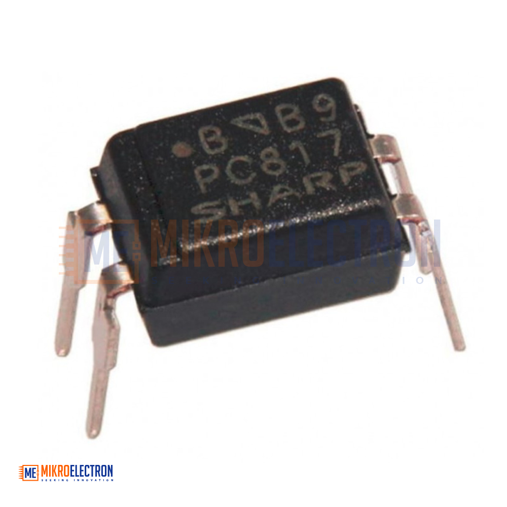
- Package Type: DIP (4-pin)
- Material: Resin housing with metal pins
- Color: Black
- Operating Type: Light-controlled switching
PCB817 Applications
As an optocoupler, the PC817 IC is advantageous for reducing noise between the input signal and electrical appliances/circuits, typical applications include:
I/O Isolation for microcontrollers
Regular electrical isolation purposes
Basic noise coupling circuit in switching circuit
IoT devices
Signal transmission
PC817 Application Circuits

A phototransistor-based optocoupler circuit is used in the upper circuit. It will function similarly to a standard DC transistor switch. A low-cost photo-transistor-based optocoupler PC817 is used in the schematic. The S1 switch will control the infrared led. When the switch is turned on, the 9V battery source will supply current to the LED through the 10k current limiting resistor. The R1 resistor controls the intensity. If we change the value and reduce the resistance, the intensity of the led will be high, resulting in a high transistor gain.
On the other side, the transistor is a phototransistor that is controlled by the internal infrared led; when the led emits infrared light, the phototransistor contacts and the VOUT becomes zero, turning off the load connected across it. It is important to remember that the transistor's collector current is 50mA according to the datasheet. The VOUT 5v is supplied by R2. The R2 resistor is a pull-up resistor.
PC817 Application Note
The output current of optocouplers is low. The maximum output current of the PC817, for example, is 50 mA. As a result, high current components (such as motors, etc.) cannot be directly connected to the optocoupler output. In such cases, a transistor must be used to supply current.
PC817 Arduino Project

Above is an Arduino interface circuit wiring example based on the PC817 optocoupler, the Arduino Uno Board, and the 2N2222 transistor.
The first 220 resistors are connected between pin 9 on the Arduino board and the positive side of the optocoupler led in the chip; this resistor reduces the voltage from the board so that it does not overpower the led and burn it out. If you use a different optocoupler than the SHARP PC817, you may need to adjust this resistor to compensate; the PC817 has a maximum led input voltage of 1.4 volts, and the resistor reduces the Arduino's 5 volts to 1.25 volts.
The second 220Ω resistor limits the current flow through the phototransistor in the chip, the SHARP PC817 will handle 35 volts at 50mA but it will get very hot and not last long under those conditions so you can put a current limiting resistor in the circuit to keep it way under those conditions.
Applications
- Signal isolation between circuits
- Switching power supplies (SMPS)
- Microcontroller input/output protection
- Industrial control systems
- Noise and interference reduction circuits
- DIY electronics and automation projects