


QTR-1RC IR Reflectance Sensor - Pololu
Out Of Stock
QTR-1RC IR Reflectance Sensor from Pololu is a compact and lightweight infrared reflectance sensor designed for line-following, edge detection, and proximity sensing applications. Featuring a single IR LED and phototransistor pair, the sensor provides a digital I/O-compatible output that can be read by measuring pulse decay time instead of using an analog input. This approach offers improved sensitivity, eliminates the need for an ADC, and enables multiple sensors to be read simultaneously. With its small size, low weight, and reliable performance, the QTR-1RC is an excellent choice for robotics, automation, and embedded system projects.
حساس QTR-1RC للأشعة تحت الحمراء من Pololu هو حساس انعكاس صغير الحجم وخفيف الوزن مصمم لتطبيقات تتبع الخطوط واكتشاف الحواف واستشعار القرب. يحتوي على مصباح أشعة تحت الحمراء ومستقبل ضوئي واحد، ويقدم خرجًا متوافقًا مع المداخل الرقمية يمكن قراءته من خلال قياس زمن اضمحلال الإشارة بدلاً من استخدام مدخل تماثلي. توفر هذه الطريقة حساسية أعلى، وتلغي الحاجة إلى محول ADC، كما تسمح بقراءة عدة حساسات في الوقت نفسه. بفضل حجمه الصغير وأدائه الموثوق، يعد خيارًا مثاليًا لمشاريع الروبوتات والأنظمة المدمجة والأتمتة.
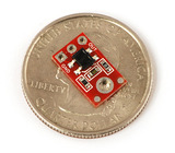
Pololu QTR-1RC IR Reflectance Sensor is a miniature reflectance sensor module designed for accurate detection of lines, edges, and nearby reflective surfaces. The module integrates a single infrared LED and phototransistor pair within a compact package measuring only 0.5 × 0.3 inches, making it suitable for installations where space is limited.
Unlike traditional analog reflectance sensors, the QTR-1RC uses a timing-based measurement method. To obtain a reading, a microcontroller charges the output node by driving the output pin high, then switches the pin to input mode and measures the time required for the signal to decay. The decay time depends on the amount of reflected infrared light received by the phototransistor.
Higher surface reflectivity causes faster discharge and shorter pulse durations, while darker or less reflective surfaces result in longer decay times. This technique offers several advantages, including increased sensitivity, elimination of analog-to-digital conversion requirements, and the ability to read multiple sensors simultaneously.
The sensor is optimized for operation at a sensing distance of approximately 3 mm, making it highly effective for line-following robots and edge detection systems. Its low power consumption and lightweight construction make it ideal for battery-powered robotic applications.
Specifications
| Specification | Value |
|---|---|
| Product Name | QTR-1RC IR Reflectance Sensor |
| Manufacturer | Pololu |
| Sensor Type | Infrared Reflectance Sensor |
| Output Type | Digital I/O Compatible Timing Signal |
| Operating Voltage | 5.0 V |
| Supply Current | 17 mA |
| IR Components | 1 IR LED + 1 Phototransistor |
| Dimensions | 0.3 × 0.5 × 0.1 in (7.6 × 12.7 × 2.5 mm) |
| Optimal Sensing Distance | 0.125 in (3 mm) |
| Maximum Recommended Distance | 0.375 in (9.5 mm) |
| Weight | 0.2 g (0.008 oz) |
| ADC Required | No |
| Output Reading Method | Pulse Decay Timing |
Applications
- Line-following robots
- Edge detection robots
- Sumo robot edge sensing
- Proximity detection systems
- Autonomous mobile robots
- Maze-solving robots
- Educational robotics projects
- Embedded system development
- Surface reflectivity measurement
- Object detection systems
- Research and development projects
- DIY electronics projects
- Automation systems
 |
|---|
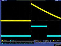
| QTR-1RC output (yellow) when 1/8" above a black line and microcontroller timing of that output (blue). |
Interfacing the QTR-1RC output to a digital I/O line
Like the Parallax QTI, this sensor requires a digital I/O line capable of driving the output line high and then measuring the time for the output voltage to decay. The typical sequence for reading a sensor is:
- Set the I/O line to an output and drive it high.
- Allow at least 10 μs for the sensor output to rise.
- Make the I/O line an input (high impedance).
- Measure the time for the voltage to decay by waiting for the I/O line to go low.
 |
These steps can typically be executed in parallel on multiple I/O lines.
With a strong reflectance, the decay time can be as low as several dozen microseconds; with no reflectance, the decay time can be up to a few milliseconds. The exact time of the decay depends on your microcontroller’s I/O line characteristics. Meaningful results can be available within 1 ms in typical cases (i.e. when not trying to measure subtle differences in low-reflectance scenarios), allowing up to 1 kHz sampling.
Our Pololu AVR library provides functions that make it easy to use these sensors with our Orangutan robot controllers; please see the QTR Reflectance Sensors section of our library command reference for more information. We also have a Arduino library for these sensors.
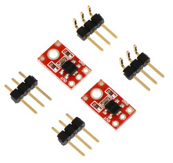
Included components
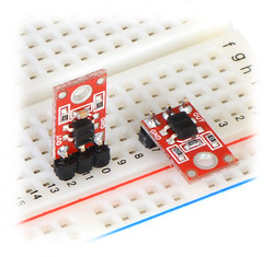
This module has a single mounting hole intended for a #2 screw (not included); if this mounting hole is not needed, this portion of the PCB can be ground off to make the unit even smaller. Each pack of two reflectance sensors includes sets of straight male header strips and right-angle male header strips, which allow you to mount them in the orientation of your choice (note: the header pins might ship as 1×6 strips that you can break into two 1×3 pieces). You can also solder wires, such as ribbon cable, directly to the pads for the most compact installation.
|
|
How it works in detail
With only four components (or five, if you count the coupled IR LED and phototransistor separately), the operation of this sensor is relatively basic. The emitter side is just an IR LED with an appropriate current-limiting resistor. The light from the emitter leaves the sensor, reflects off a nearby surface, and returns to the detector.
The detector side is a resistor-capacitor (RC) circuit, where the resistance comes from the phototransistor and is a measure of the incident infrared light, and the decay time is proportional to the resistance. The first step of the sensor-reading process—driving the sensor output high—discharges the integrated 10 nF capacitor and puts both sides at the same voltage (VIN). Alternatively, you can think of this as “charging the output node”, and it is functionally equivalent to charging a capacitor with one side connected to ground. Once you are no longer supplying an external voltage to the output pin, the capacitor can slowly charge through the phototransistor, with the rate of charging being a function of the phototransistor’s resistance (which is in turn a function of the incident IR). As the capacitor charges, the voltage on the output side drops, eventually reaching zero when the capacitor is fully charged. Alternatively, you can think of this as “discharging the output node”, and it is functionally equivalent to discharging a capacitor with one side connected to ground.
The 220 Ω resistor on the OUT line serves to limit the current flow, making it possible for a microcontroller output to safely charge the output node prior to each reading. It has very little effect on the sensor output.