Search your product from here


1 / 3

ORP Module with Electrode Water Quality Detection Analog Output for Arduino/51/STM32
5.0(1 review)
JD67.00
Module power supply: +5.00VMeasuring range: -2000mV-2000mVOutput voltage range: 0-4VMeasuring temperature: 5-70℃Measurement accuracy: ±10mV (25℃)Response time: <20secResponse time: <1minORP potentiometer interface: BNC interfaceModule size: 35mm × 26mm Instructions: Value in ORP standard solution: 222±15mV (25℃)The temperature coefficient characteristics of the OR...
Module power supply: +5.00V
Measuring range: -2000mV-2000mV
Output voltage range: 0-4V
Measuring temperature: 5-70℃
Measurement accuracy: ±10mV (25℃)
Response time: <20sec
Response time: <1min
ORP potentiometer interface: BNC interface
Module size: 35mm × 26mm


Instructions:
Value in ORP standard solution: 222±15mV (25℃)
The temperature coefficient characteristics of the ORP standard solution are shown in the following table (3.5mol/L KCL)

Because there is zero drift voltage in the ORP sensor module, in order to obtain more accurate measurement values and improve the measurement accuracy, it is recommended to perform zero calibration before measurement. The specific steps are as follows:
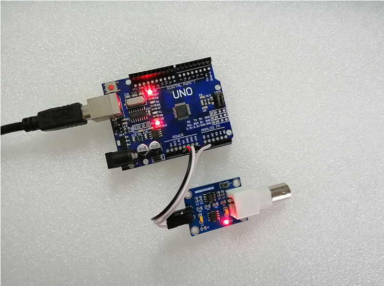
step 1: connect the ORP sensor module and the processor (do not connect the ORP potentiometer at this time);

Step 2: Burn calibration routine.
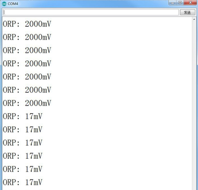
Step 3: open the serial debugging assistant, you can see the currently printed ORP value. Press and hold the zero calibration button on the ORP sensor module. After the serial port monitor print data is stable, record the offset value. For example, the serial port prints out: "ORP: 17mV", then modify "#define OFFSET0" in the sample program to "Hdefine OFFSET 17". The purpose of modifying the offset is to eliminate the zero drift voltage generated by the operational amplifier and improve the measurement accuracy. After modifying the sample program, recompile and download, and the calibration is completed.

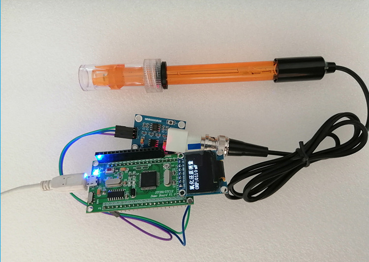
Step 4: Connect the ORP electrode to the BNC interface of the ORP sensor module. After rewriting the revised program, the ORP value of the solution can be measured.