
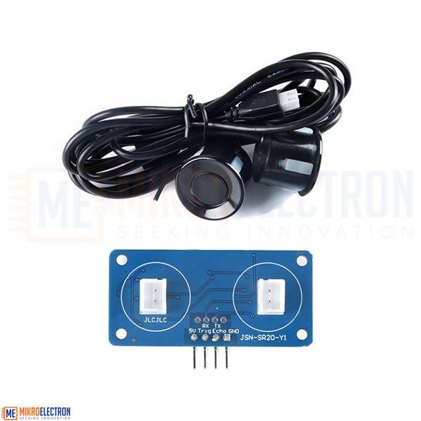
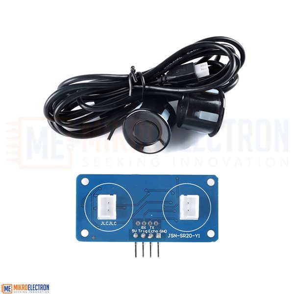
Upgrade Waterproof Ultrasonic Ranging Module JSN-SR20-Y1 Dual Probe
JSN-SR20-Y1 dual-head ranging module can provide 2 cm-500cm the non-contact distance sensing function, the ranging accuracy can reach high3mm; The module consists of ultrasonic sensor integrating receiving and dispatching and control circuit. The usage of Model 1 is the same as that of our company HC-SR04 the module aims to reveal the volume.This product adopts industrial grade double waterproof u...
JSN-SR20-Y1 dual-head ranging module can provide 2 cm-500cm the non-contact distance sensing function, the ranging accuracy can reach high3mm; The module consists of ultrasonic sensor integrating receiving and dispatching and control circuit. The usage of Model 1 is the same as that of our company HC-SR04 the module aims to reveal the volume.
This product adopts industrial grade double waterproof ultrasonic probe design, waterproof type, stable performance, Qianrong all MCU work in the market.
Super close distance, the blind area is only 2cm. Stable ranging is the powerful basis for this product to successfully enter the market.
- specifications and parameters:
| pulse output | the serial output | |
| working voltage | DC :3.0-5.5V | |
| working current | less8mA | |
| the probe frequency | 40kHz | |
| the farthest range | 500cm | |
| recently range | 2cm | |
| long-distant accuracy | ± 1cm | |
| resolution | 3mm | |
| to measure the angle | 60 the degree | |
| the input trigger signal | 1,20uS the above TTL pulse 2 and the serial port to send instructions0X55 | |
| the output of the echo signal | output pulse width level signal, or TTL | |
| connection mode | 3-5.5V ( the positive pole) Trig ( the control terminal)RX Echo(Output) TX GND(The negative pole of the power supply | |
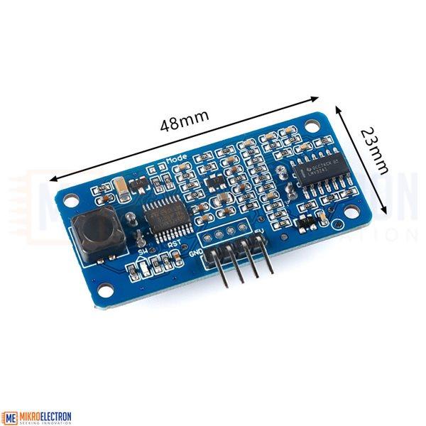
| product Size | L48*W23*H10 mm | |
| operating temperature | -20℃-+ 70℃ | |
| part color | PCB board is blue | |
- function output mode description:
| serial Number | output mode | mode-bit electronic resistance resistance | note |
| the mode 0 | PWM output | suspended | the factory default |
| mode 1 | UART auto output | 47 kΩ | |
| mode 2 | UART controlled output | 120 kΩ | directive 0X55 |
| mode 3 | PWM auto output | 200 kΩ | cycle 200MS |
| mode 4 | low-power PWM output | 360 kΩ | |
| the Mode 5 | switch output | 470 kΩ |

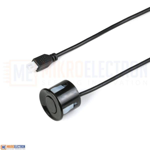
with line probe: The standard line length is 1 meter
mode 0:Moode = open that is no welding. The mode as follows
1. basic working principle:
(1) use IO port TRIG to trigger ranging, and present high-power level signals with a minimum of 20US.
(2) the module automatically sends 8 square waves of 40kHz to automatically detect whether there is a signal return;
(3) if there is a signal, ECHO outputs a high level through the IO port. The duration of the high level is the time when the ultrasonic wave returns from sending it. Test distance = (high level Time * sound velocity (348M/S))/2;
(4) after the module is triggered for distance measurement, if no ECHO is received (the reason is beyond the measured range or the probe does not face the measured object), the ECHO Port will automatically become low after 40ms, marks the end of this measurement, whether successful or not.
2 Ultrasonic timing diagram:
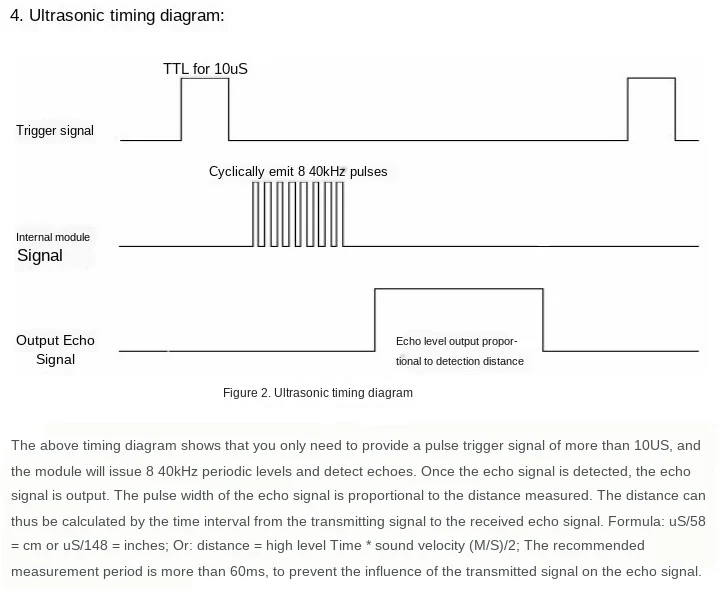
figure II, ultrasonic timing
12: Mode=47K UART automatic output
UART the automatic output mode outputs the distance value (hexadecimal number) according to UART Communication Format. This mode does not need additional trigger signal, and the module can
automatically measure once every 100ms, each measurement is completed at the TX pin output to measure the distance value.
(1) pin definition
| serial Number | cement grade | pin description | note |
| 2 | TX | UART output pins | |
| 3 | RX | no |
(2) communication protocol
| UART | the baud rate | check bits | data bits | stop |
| TTL | 9600 bps | N | 8 | 1 |
(3) Format Description
| the frame data | description | byte |
| the frame header | fixed0XFF | 1 byte |
| H_DATA | the distance data of the high8 bit | 1 byte |
| L_DATA | the distance data of low8 bit | 1 byte |
| SUM | data verification | 1 byte |
note: the checksum only retains the low 8 bits of the cumulative value
For example:
product response FF 07 A1 A7
where check code SUM = A7 =(0x07 0x1 0Xff)& 0x00ff
0x07 high data of distance;
0xA1 low data for distance;
distance value is 0 x07A1; Converted to decimal is 1953; Unit is: MM
note: If the module cannot measure the data or outputs 0 beyond the distance range. After the Led is powered on, it enters the working mode and automatically flashes by 100ms.
mode2: Mode=120K UART the controlled output
UART the controlled output mode outputs the measured distance value (hexadecimal number) according to UART Communication Format. This mode needs to add trigger 0x 55 signal to RX foot, and measures it every time the module receives an instruction, each measurement is completed at the TX pin output to measure the distance value. The instruction trigger cycle is larger than 60ms
(1) pin definition
| serial Number | cement grade | pin description | note |
| 2 | TX | UART output pins | |
| 3 | RX | UART controlled to receive a foot (Command 0X55) |
(2) communication protocol
| UART | the baud rate | check bits | data bits | stop |
| TTL | 9600 bps | N | 8 | 1 |
(3) Format Description
| the frame data | description | byte |
| the frame header | fixed0XFF | 1 byte |
| H_DATA | the distance data of the high8 bit | 1 byte |
| L_DATA | the distance data of low8 bit | 1 byte |
| SUM | data verification | 1 byte |
note: the checksum only retains the low 8 bits of the cumulative value
for example:
product response FF 07 A1 A7
where check code SUM = A7 =(0x07 0x1 0Xff)& 0x00ff
0x07 high data of distance;
0xA1 low data for distance;
distance value is 0 x07A1; Converted to decimal is 1953; Unit is: MM
note: If the module cannot measure the data or outputs 0 beyond the distance range. After the Led is powered on, the command light will be on every time it is triggered. The frequency is the same as the trigger cycle.
mode 3: Mode=200K high level (PWM) pulse width automatic output
pulse width PWM with automatic output, the module automatically measures at the interval of 200ms, and outputs the high level of pulse width corresponding to the distance after the test. Calculation distance mode reference mode 1
(1) pin definition
| serial Number | cement grade | pin description | note |
| 2 | Trig | - | |
| 3 | Echo | high-level pulse width output |
Ø mode4:Mode=360K low Power (PWM) high level pulse width controlled output
in the mode of low power consumption, the closing dog of the module is disabled, and this mode is suitable for users powered by batteries. The static electricity consumption is less than 70UA, and the working ranging method is the same as that of Mode 1.
(1) pin definition
| serial Number | cement grade | pin description | note |
| 2 | Trig | the trigger control pin | |
| 3 | Echo | high-level pulse width output |
mode5: Mode=470K switch output
the job description module will set a threshold value at the factory, which defaults to 1.5 meters. The module conducts ranging once every 200ms, when the distance value of the detected target is less than the set threshold value, Echo pin output high level, the current detected distance value is greater than the set threshold value, Echo pin output low level, in order to improve the stability, the factory default is to detect the distance value of the target twice in a row is less than the set threshold value to determine the range to target of detection is less than the set threshold value; Module Echo the PIN only outputs high and low level signals without drive capability. Triode drive relay should be added during application. If there are special requirements to modify the threshold value or other settings, special instructions are required when purchasing.
(1) pin definition
| serial Number | cement grade | pin description | note |
| 2 | Trig | - | |
| 3 | Echo | switch the High Level Output pin | the obstacle is H, otherwise L |
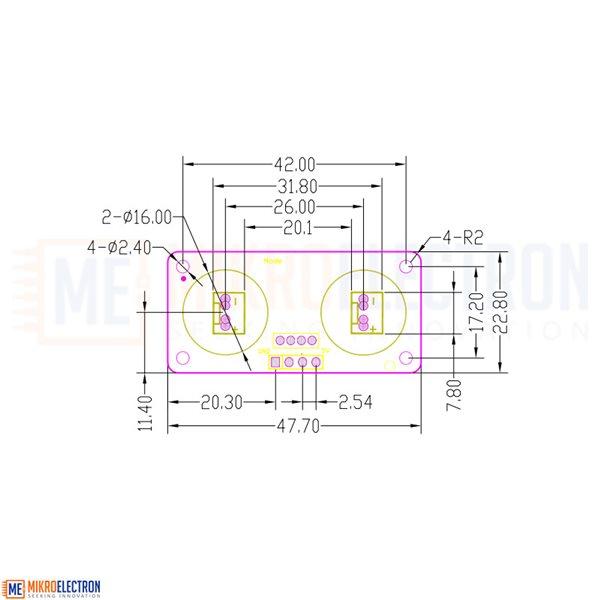
- size
