12V Voltage Protection Module & Battery Controller Charge Discharge 0-15V Tester Switch Relay Module


Description:
DC 12V Overvoltage Undervoltage Protection Module Voltage Comparator Battery Charge Discharge Controller 0-15V Tester Switch Relay Module
- It is a DC 12V under-voltage protection module.
- This board is a voltage detection module for the common negative electrode (the common negative electrode for detection and power supply),and the detected voltage must have a driving capacity of 2mA.
Parameter:
- Product Name: DC 12V Under-Voltage Protection Module
- Power Supply Voltage: DC 12V
- Voltage Detection Range: m0V~15V
- Voltage Resolution:0.05V
- Detection Interface Withstand Voltage:25V
- Work Temperature:-25℃~85℃
- Work Humidity:5%~95%RH
- Size:51*34*21mm
Applicable:
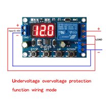
The initial module power-on relay is OFF, and the load does not work.
When it is detected that the voltage is lower than the RA1 (low limit) setting or it is detected that the voltage is higher than the RA2 (high limit) setting, the relay is ON and the load is working.
After the relay is ON, the load can be released only when it is detected that the voltage is between the RA1 (low limit) and RA2 (high limit) settings.
After the relay is released, repeat the second and third steps to test the voltage repeatedly.
Module Debugging Settings:
- Test point: TP1 test point, test point for detecting the input voltage of the interface (divided by a fixed resistor)
- TP3 test point ,RA1 (low limit) adjustable resistance adjustable voltage test point.
- TP4 test point, RA2 (high limit) adjustable resistance adjustable terminal voltage test point.
- TP2 test point, RA3 (delay time) adjustable resistance adjustable terminal voltage test point.
- Tools required: multimeter, adjustable power supply, power supply, small flat screwdriver, etc. (not included in this product)
- Setting method one: Quick debugging setting (try to use this method as much as possible, this method is accurate)
- The module is normally powered, and the input low limit set voltage is detected. Adjust RA1 to adjust the voltage at TP3 to be equal to the voltage at TP1.
- The module is normally powered, and the input high limit set voltage is detected. Adjust RA2 to make the voltage at TP4 equal to the voltage at TP1.
- After the adjustment is completed, power on the module again.
- Pay attention to the lower limit set voltage value, not higher than the high limit voltage set value (TP4 voltage is greater than TP3 voltage).
- The test point voltage is for the common ground GND, which is the negative pole of the power supply.
- When the multimeter measures, the black pen is connected to GND or the power supply negative pole, and the red pen is connected to the test points TP1,TP3,TP4 to measure the voltage.
- Example: Suppose you set the low limit of 12v.
- The module is normally powered. Use an adjustable power supply to provide a 12v voltage to the detection interface. Use a multimeter to measure the voltage at the TP1 test point and note the voltage value.Then adjust the adjustable value of RA1 so that the voltage at point TP3 is equal to the voltage at point TP1.
- Suppose you set a high limit of 14v
- The module is normally powered. Use an adjustable power supply to test the interface with a 14v voltage. Use a multimeter to measure and measure the voltage at the TP1 test point and note the voltage value.Then adjust the adjustment of RA2 to make the TP4 voltage equal to the TP1 point voltage value just measured
- Setting method two: Step-down ratio calculation setting
- The module supplies power normally. Input any voltage "U" within the detection range into the detection interface and measure it with a digital multimeter.
- At this point, the voltage value at TP1 and the voltage value of "U", get a fixed step-down ratio VR=U/TP1
- TP3=Low limit setting voltage/VR
- TP4=High limit setting voltage/VR
- Adjust RA1 and RA2 respectively to make the TP3 and TP4 voltages equal to the calculated voltage values,and power on the module again.
- Be careful not to set the low limit setting voltage higher than the high limit voltage setting (TP4 voltage must be greater than TP3 voltage.
- The test point voltage is for the common ground GND, which is the negative pole of the power supply. When the multimeter measures, the black pen is connected to the GND or the negative pole of the power supply, and the red pen is connected to the test points TP1,TP3,TP4 to measure the voltage.
- Setting method three: Calculation setting of step-down ratio formula
- TP3=Low limit setting/2
- TP4 voltage=high limit setting/2
- Adjust RA1 and RA2 respectively to make the TP3 and TP4 voltages equal to the calculated voltage values, and power on the module again.
- Be careful not to set the low limit setting voltage higher than the high limit voltage setting (TP4 voltage must be greater than TP3 voltage.
- The test point voltage is for the common ground GND, which is the negative pole of the power supply.
- When the multimeter measures, the black pen is connected to GND or the power supply negative pole, and the red pen is connected to the test points TP1,TP3,TP4 to measure the voltage.
Features:
- It has working status indicator
- It can adjust parameter settings
- The relay control output
- It supports under-voltage protection
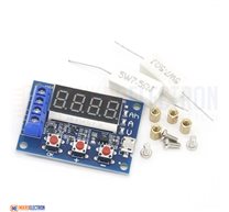
Kit include:
1 x DC 12V Under-Voltage Protection Module
1 x XH2.54-2P 20cm Wire
Related Products


subscribe to our weekly newsletter
We are an online electronics store based in Jordan-Amman. The products we sell ranges from electronic products to modules and much more.
- AMMAN, Jordan. University Street, Khalifa Building 3rd floor
- Mobile: +962 7900 621 96, +962 65344772, +9627 8877 5522
- Phone: +962 6 5344772
- Fax: +96265344778
- Email: info@mikroelectron.com

2024 © Mikroelectron. ALL Rights Reserved. | Distributor Area
Made With By Tashfier.