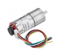
25GA-370 12V 125 RPM DC Motor with Encoder

Description:
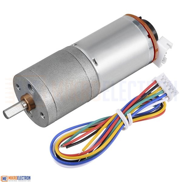
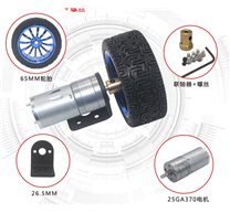
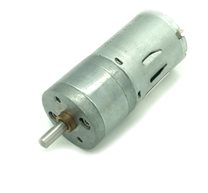
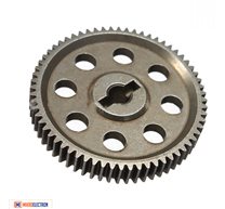
The 25GA 12V 125 RPM DC Motor with Encoder and Gearbox is ideal for closed loop speed or position control projects such as: inverted pendulum, autonomous mobile robot, DC servo motor, conveyor belt and more. The device is composed of three parts: the DC motor, the gearbox and the quadrature encoder. The DC motor operates at a nominal voltage of 12V. The metal gearbox serves the function of reducing the input speed and increasing the output torque. The motor and gearbox are made of metal for durability and strength. The encoder serves as a speed and direction sensor, it works using two Hall effect sensors.
The DC motor works with voltages between 5V and 12V, the output torque and speed vary according to the applied voltage. When working with the nominal voltage of 12V, the output angular speed will be 1000RPM (revolutions per minute). To work with a microcontroller such as Arduino, PIC, Teensy, NodeMCU or Raspberry Pi we will need to use a power driver and an external power supply. For the Driver we can choose an H bridge such as the L298N Driver , the VNH2SP30 Driver , or the BTS7960 Driver, which will allow us to control the direction of rotation and the speed through PWM. In the case that it is only necessary to rotate the motor in one direction we can use a 30A Mosfet Driver that also allows us to regulate the speed by PWM. For the power supply we must use a source with the capacity to deliver at least 2 amps constantly, such as the 12V/8A Switching Power Supply . We do not recommend using the 5V output of our Arduino, nor powering the motor with the PC's USB port, this is because the current required by the motor is greater than what these devices can deliver.
The encoder consists of a multi-pole magnetic disk attached to the shaft of the DC motor and two Hall effect sensors. When the DC motor rotates, the magnetic disk also rotates and the magnetic poles of the disk pass in front of the Hall sensors that emit a digital pulse ("tick") each time they detect a positive magnetic pole. Since the disk has 22 alternating poles, then for each revolution each Hall sensor will emit 11 pulses or "ticks". The two Hall sensors (A and B) are 90º out of phase and their square wave outputs will also be 90º out of phase, this is known as a quadrature encoder. The wave offset is useful to detect the direction of rotation of the motor, because when rotating in one direction wave A will precede wave B and in the other direction of rotation wave B will precede wave A. To work with Arduino Uno or Nano, pins 2 and 3 must be used, which correspond to external interruptions; for other Arduino models, we must check which are the appropriate pins.
TECHNICAL SPECIFICATIONS
Motor supply voltage: 12V DC
Encoder supply voltage: 3.3V - 5V DC
No-load current consumption: 100mA
Nominal current consumption: 300mA
Current consumption stopped axis: 1000mA (Peak)
Rotational speed: 125RPM @12V
Gear ratio: 1:12
Encoder: Two-phase Hall
Hall Resolution: Hall x Ratio 34.02 = 341.2 PPR
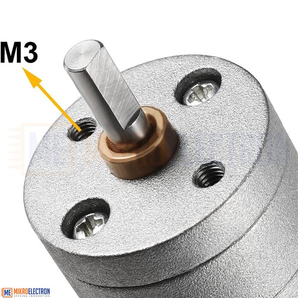
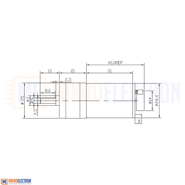
Shaft diameter: 4mm, D-shaped shaft
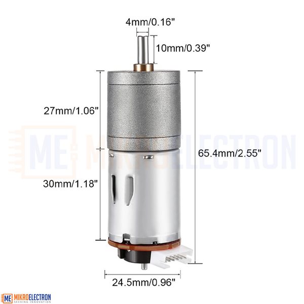
Outer diameter of the housing: 25 mm
Dimensions: D25mm*L71mm
Weight: 95 grams
PINES
Pin 1: (Vmot-) Motor Terminal -
Pin 2: (GND) Encoder GND
Pin 3: Phase A Encoder Output
Pin 4: Phase B Encoder Output
Pin 5: (3.3 V or 5 V) VCC Encoder
Pin 6: (Vmot+) Motor + Terminal

Kit include:
1 x 12V 125 RPM DC Motor with Encoder
Related Products

subscribe to our weekly newsletter
We are an online electronics store based in Jordan-Amman. The products we sell ranges from electronic products to modules and much more.
- AMMAN, Jordan. University Street, Khalifa Building 3rd floor
- Mobile: +962 7900 621 96, +962 65344772, +9627 8877 5522
- Phone: +962 6 5344772
- Fax: +96265344778
- Email: info@mikroelectron.com


2024 © Mikroelectron. ALL Rights Reserved. | Distributor Area
Made With By Tashfier.