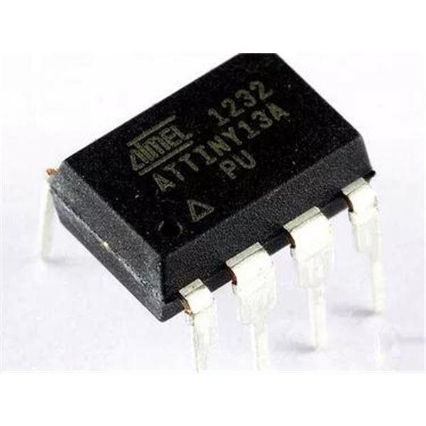
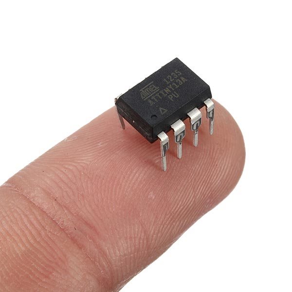
ATTINY13A-PU DIP-8
Description:
ATTINY13A-PU DIP-8
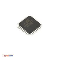
The Atmel picoPower 8-bit AVR RISC-based microcontroller featuring 1KB of ISP Flash, 64-byte EEPROM, 64-byte SRAM, 32-Byte register file, and 4-channel 10-bit A/D converter. The device achieves up to 20 MIPS throughput at 20 MHz at 1.8-5.5 V operation.
By executing powerful instructions in a single clock cycle, the ATtiny13A achieves throughputs approaching 1 MIPS per MHz allowing you to optimize power consumption versus processing speed.
Key Parameters
Flash (kBytes):
1 kBytes
Pin Count:
8
Max. Operating Freq. (MHz):
20 MHz
CPU:
8-bit AVR
Hardware QTouch Acquisition:
No
Max I/O Pins:
6
Ext Interrupts:
6
USB Speed:
No
USB Interface:
No
Graphic LCD:
No
![]()
شرح :
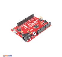
0. Turn the Arduino into a AVRISP
(AVR is a family of microcontrollers. ISP means In System Programmer)
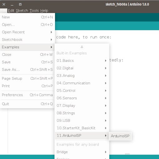
Open Arduino IDE -> File -> Examples -> 11.ArduinoISP ->ArduinoISP and upload to Arduino
1. Install hardware package for ATtiny13
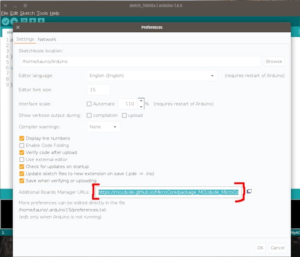
1.1 Open Arduino IDE -> File -> Preferences go to Additional Boards Manager URLsand copy this:
https://mcudude.github.io/MicroCore/package_MCUdude_MicroCore_index.json
Ok.
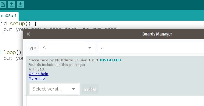
1.2 Open Arduino IDE -> Tools -> Board -> Boards manager. Find MicroCore and click Install.
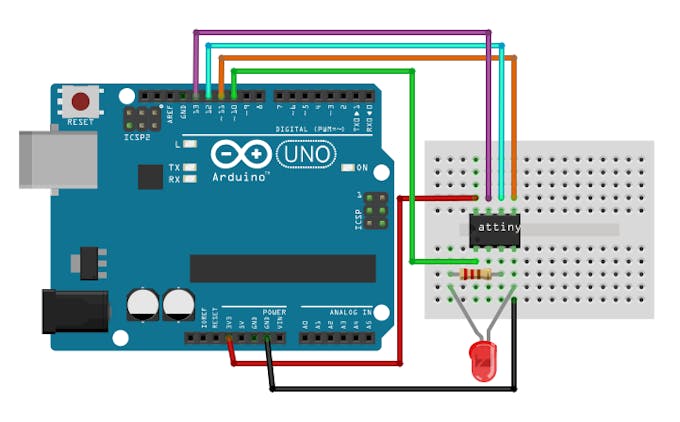
2. Connect the hardware
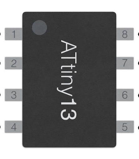
- ATtiny13A leg 1 -> Arduino 10
- ATtiny13A leg 5 -> Arduino 11
- ATtiny13A leg 6 -> Arduino 12
- ATtiny13A leg 7 -> Arduino 13
- ATtiny13A leg 8 -> 5v
- ATtiny13A leg 4 -> Ground (GND)
LED and resistor is needed only for testing to see does uploaded example code works or not.
3. Arduino IDE settings
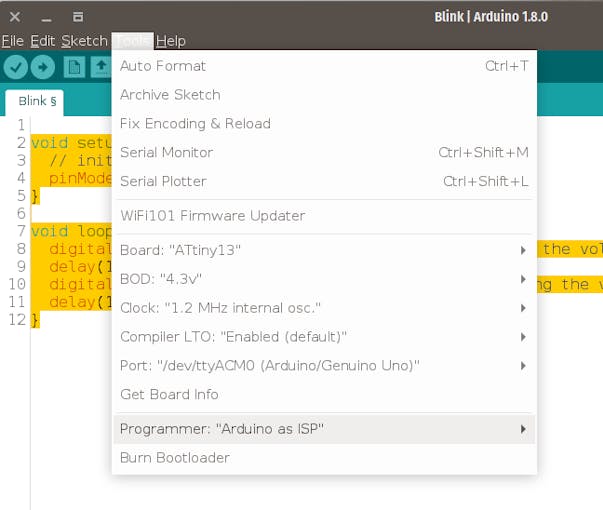
Go to Arduino IDE -> Tools and select:
- Board: ATtiny 13
- BOD: 4.3v
- Clock: 1.2 MHz internal osc.
- Compiler LTO: Enable
- Port: (Your Arduino port)
- Programmer: Arduino as ISP
4. Burn Bootloader
(You only need to do this once per chip)
Go to Arduino IDE -> Tools -> Burn Bootloader
You might see an error, but ignore it.
5. Upload sketch
Copy Blink sketch:
void setup() {
 // initialize pin 4 (ATtiny leg 3) as an output.
 pinMode(4, OUTPUT);
}
void loop() {
 digitalWrite(4, HIGH);   // turn the LED on (HIGH is the voltage level)
 delay(1000);             // wait for a second
 digitalWrite(4, LOW);    // turn the LED off by making the voltage LOW
 delay(1000);             // wait for a second
}
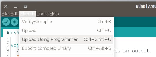
Go to: Arduino IDE -> Sketch -> Upload Using Programmer
Note:
use 1.2mhz clock
Documents:
library use 1.2mhz clock
Related Products
subscribe to our weekly newsletter


