Arduino Motor Shield
Description:
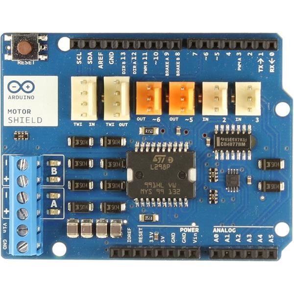
The Arduino Motor Shield is based on the L298 which is a dual full-bridge driver designed to drive inductive loads such as relayssolenoidsDC and stepping motors. It lets you drive two DC motors with your Arduino boardcontrolling the speed and direction of each one independently. You can also measure the motor current absorption of each motoramong other features. The shield is TinkerKit compatiblewhich means you can quickly create projects by plugging TinkerKit modules to the board.
Power
The Arduino Motor Shield must be powered only by an external power supply. Because the L298 IC mounted on the shield has two separate power connectionsone for the logic and one for the motor supply driver. The required motor current often exceeds the maximum USB current rating.
External (non-USB) power can come either from an AC-to-DC adapter (wall-wart) or battery. The adapter can be connected by plugging a 2.1mm center-positive plug into the Arduino's board power jack on which the motor shield is mounted or by connecting the wires that lead the power supply to the Vin and GND screw terminalstaking care to respect the polarities.
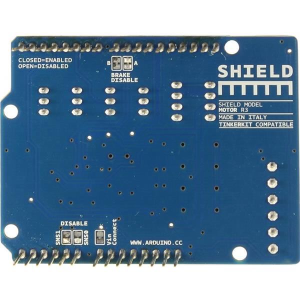
To avoid possible damage to the Arduino board on which the shield is mountedwe reccomend using an external power supply that provides a voltage between 7 and 12V. If your motor require more than 9V we recommend that you separate the power lines of the shield and the Arduino board on which the shield is mounted. This is possible by cutting the "Vin Connect" jumper placed on the back side of the shield. The absolute limit for the Vin at the screw terminals is 18V.
The power pins are as follows:
Vin on the screw terminal blockis the input voltage to the motor connected to the shield. An external power supply connected to this pin also provide power to the Arduino board on which is mounted. By cutting the "Vin Connect"jumper you make this a dedicated power line for the motor.
GND Ground on the screw terminal block.
The shield can supply 2 amperes per channelfor a total of 4 amperes maximum.
Input and Output
This shield has two separate channelscalled A and Bthat each use 4 of the Arduino pins to drive or sense the motor. In total there are 8 pins in use on this shield. You can use each channel separately to drive two DC motors or combine them to drive one bipolar stepper motor.
If you don't need the Brake and the Current Sensing and you also need more pins for your application you can disable this features by cutting the respective jumpers on the back side of the shield.
The additional sockets on the shield are described as follow:
Screw terminal to connect the motors and their power supply.
2 TinkerKit connectors for two Analog Inputs (in white)connected to A2 and A3.
2 TinkerKit connectors for two Aanlog Outputs (in orange in the middle)connected to PWM outputs on pins D5 and D6.
2 TinkerKit connectors for the TWI interface (in white with 4 pins)one for input and the other one for output.
Motors connections
Brushed DC motor. You can drive two Brushed DC motors by connecting the two wires of each one in the (+) and (-) screw terminals for each channel A and B. In this way you can control its direction by setting HIGH or LOW the DIR A andDIR B pinsyou can control the speed by varying the PWM A and PWM B duty cycle values. The Brake A and Brake B pinsif set HIGHwill effectively brake the DC motors rather than let them slow down by cutting the power. You can measure the current going through the DC motor by reading the SNS0 and SNS1 pins. On each channel will be a voltage proportional to the measured currentwhich can be read as a normal analog inputthrough the function analogRead() on the analog input A0 and A1. For your convenience it is calibrated to be 3.3V when the channel is delivering its maximum possible currentthat is 2A.
Physical Characteristics
The maximum length and width of the Motor Shield PCB are 2.7 and 2.1 inches respectively. Four screw holes allow the board to be attached to a surface or case. Note that the distance between digital pins 7 and 8 is 160 mil (0.16")not an even multiple of the 100 mil spacing of the other pins.
Features:
- Operating Voltage : 5V to 12V
- Motor controller: L298P, Drives 2 DC motors or 1 stepper motor
- Max current : 2A per channel or 4A max (with external power supply)
- Current sensing : 1.65V/A
- Free running stop and brake function
Documents:
- datasheet
- EAGLE files: arduino_MotorShield_Rev3-reference-design.zip
- Schematic: arduino_MotorShield_Rev3-schematic.pdf
Related Products
subscribe to our weekly newsletter
We are an online electronics store based in Jordan-Amman. The products we sell ranges from electronic products to modules and much more.
- AMMAN, Jordan. University Street, Khalifa Building 3rd floor
- Mobile: +962 7900 621 96, +962 65344772, +9627 8877 5522
- Phone: +962 6 5344772
- Fax: +96265344778
- Email: info@mikroelectron.com

2024 © Mikroelectron. ALL Rights Reserved. | Distributor Area
Made With By Tashfier.