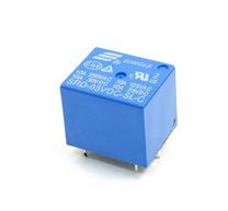
HRS1H-S-DC5V Relay
Description:
DESCRIPTION
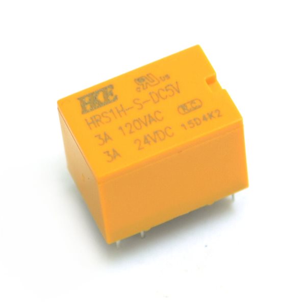
The HRS1H-S-DC5V is a 5V relay that can control up to 125/250VAC or up to 24VDC at up to 3A or 90W.
PACKAGE INCLUDES:
- HRS1H-S-DC5V 3A Relay
KEY FEATURES OF HRS1H-S-DC5V 3A RELAY:
- Switch AC up to 125/250VAC @ up to 3A
- Switch DC up to 24VDC @ up to 3A
- Switch maximum of 90W total power
- Normally Open (NO) and Normally Closed (NC) contacts
- 5V @ 40mA coil operation
- Standard 0.1″ lead spacing compatible with proto boards.
These small relays are handy for home-brew projects that need to switch modest amounts of AC or DC power. Take note that the maximum power of the device is 90W, so if switching 110VAC, the maximum allowable current would be 0.8A. If you are switching 12VDC, then you can switch up to the full 3A.
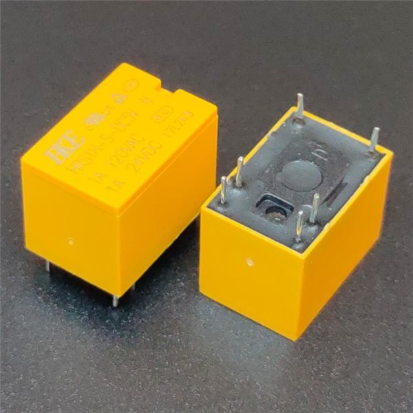
 The relay has six pins that are conveniently spaced on 0.1″ centers which allow them to mount in a standard proto / perf board. The pin layout and length will not allow them to be used in a solderless breadboard unless wires are tacked on.
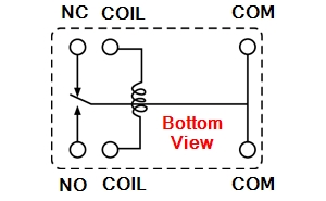
The pinout drawing to the right is shown when looking at the bottom (pin side) of the relay.
- COM – Common pin. These pins connect to either the power source or ground depending on how the circuit is connected. Only one pin needs to be connected.
- NC – Normally Closed pin. When the relay is un-energized, the COM pin is connected to the NC pin. When the relay is energized, this connection is opened.
- NO – Normally Open pin. When the relay is un-energized, the COM pin is disconnected from the NO pin. When the relay is energized, this connection is closed.
- COIL – Connecting one side to 5V and the other side to ground energizes the relay. The two pins are interchangeable.
The relay has a 125 ohm coil, so maximum current draw to energize the relay is 40mA. Most MCU pins are limited to 20mA, so the relay should not be driven directly off a digital pin of an MCU. A small NPN transistor like the 2N3904 or 2N2222 can be used to safely increase the current drive to the relay. A base current limiting resistor is normally used to provide some protection for the MCU pin. This value is not critical in this application and we are using a 2.2K in our example circuit.
To protect the transistor when the relay is de-energized, a flyback diode is recommended across the relay coil windings as shown in the schematic. The cathode of the diode is connected to the 5V side of the coil so that it is reverse biased during normal operation and conducts when the coil is de-energized and a reverse voltage occurs when the coil magnetic field collapses which could otherwise damage the transistor. A small diode like the 1N4148 is normally enough though a beefier 1N400x won’t hurt.
In addition, if the relay is controlling an inductive load like a DC motor, a flyback diode across the relay contacts on the output side should be used to shunt the current safely around the relay contacts when it is de-energized to avoid possible welding and sticking of the relay contacts. Placing the diode directly across the motor terminals is preferred. A beefier diode like a 1N400x is normally called for.
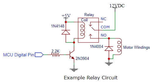
In the example circuit, the relay is activated with a logic HIGH signal from the MCU.
Notes:
- If working with AC line voltages, care should be taken to insulate or otherwise guard against possible contact with dangerous voltages.
Related Products
subscribe to our weekly newsletter
We are an online electronics store based in Jordan-Amman. The products we sell ranges from electronic products to modules and much more.
- AMMAN, Jordan. University Street, Khalifa Building 3rd floor
- Mobile: +962 7900 621 96, +962 65344772, +9627 8877 5522
- Phone: +962 6 5344772
- Fax: +96265344778
- Email: info@mikroelectron.com


2024 © Mikroelectron. ALL Rights Reserved. | Distributor Area
Made With By Tashfier.