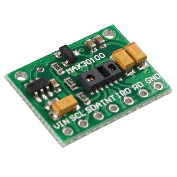
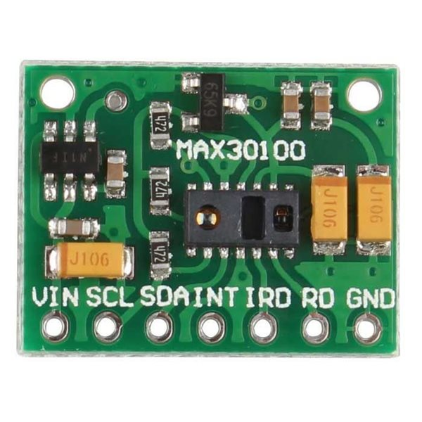
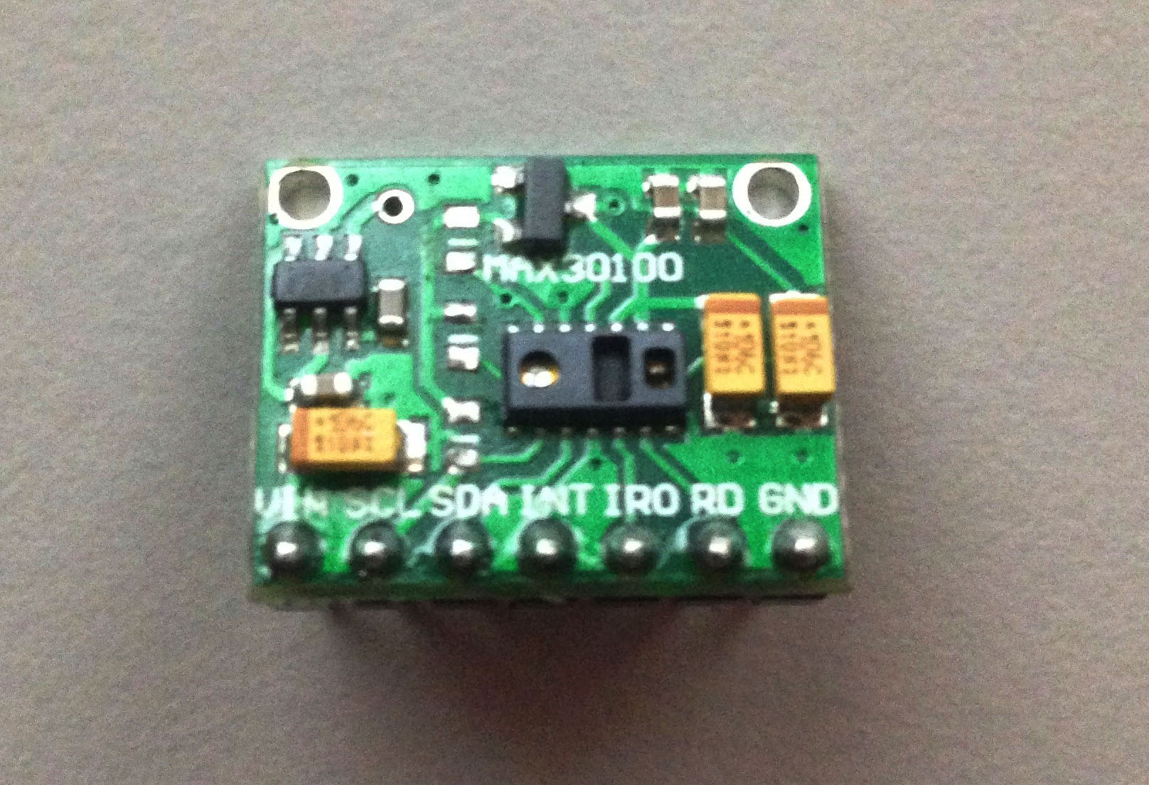
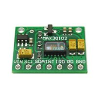
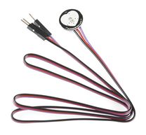
MAX30100 Pulse Oximeter Heart-Rate Sensor Module
Description:
The MAX30100 is an integrated pulse oximetry and heart rate monitor sensor solution. It combines two LEDs, a photodetector, optimized optics, and low-noise analog signal processing to detect pulse oximetry and heart-rate signals.
The MAX30100 operates from 1.8V and 3.3V power supplies and can be powered down through software with negligible standby current, permitting the power supply to remain connected at all times.
Applications:
- Wearable Devices
- Fitness Assistant Devices
- Medical Monitoring Devices
Benefits and Features:
- Complete Pulse Oximeter and Heart-Rate Sensor Solution Simplifies Design Integrated LEDs, Photo Sensor, and High-Performance Analog Front -End
Tiny 5.6mm x 2.8mm x 1.2mm 14-Pin Optically Enhanced System-in-Package
- Ultra-Low-Power Operation Increases Battery Life for Wearable Devices Programmable Sample Rate and LED Current for Power Savings
Ultra-Low Shutdown Current (0.7μA, typ)
- High SNR Provides Robust Motion Artifact Resilience Integrated Ambient Light Cancellation
- High Sample Rate Capability
- Fast Data Output Capability

| Purple MAX30100 Module | Arduino UNO/Nano |
| VIN | 5V |
| GND | GND |
| SCL | A5 |
| SDA | A4 |
| INT | D2 |
You see, this module uses this schematic:
The MAX30100 IC uses 1.8V for VDD and this particular module uses two regulators to achieve this voltage. Nothing wrong with that. However, if you look closely, the SCL and SDA pins are pulled-up via the 4.7k ohm resistors to 1.8V! This means it won't work well with microcontrollers with higher logic levels.
The solution is to remove the resistors from the board (encircled on the image below) and attach external 4.7k ohms resistors instead.
Here's my board with the resistors removed:
After removing the resistors, you can now connect this module to the Arduino UNO using this wiring diagram:

For the sketch, I used this library. The library provides a couple of examples. This is the most basic sketch
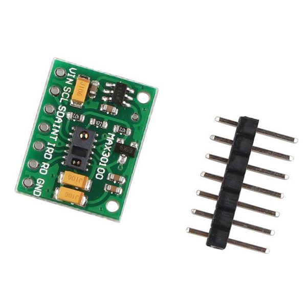
Kit include:
1 x Max30100 module
Documents:
MAX30100_PulseOximeter Library
Mikroelectron Code:
#include <Wire.h>
#include "MAX30100_PulseOximeter.h"
#define REPORTING_PERIOD_MS 1000
// PulseOximeter is the higher level interface to the sensor
// it offers:
// * beat detection reporting
// * heart rate calculation
// * SpO2 (oxidation level) calculation
PulseOximeter pox;
uint32_t tsLastReport = 0;
// Callback (registered below) fired when a pulse is detected
void onBeatDetected()
{
Serial.println("Beat!");
}
int x=3;
void setup()
{
Serial.begin(115200);
pinMode(3,OUTPUT);
Serial.print("Initializing pulse oximeter..");
// Initialize the PulseOximeter instance
// Failures are generally due to an improper I2C wiring, missing power supply
// or wrong target chip
if (!pox.begin()) {
Serial.println("FAILED");
for(;;);
} else {
Serial.println("SUCCESS");
}
// The default current for the IR LED is 50mA and it could be changed
// by uncommenting the following line. Check MAX30100_Registers.h for all the
// available options.
// pox.setIRLedCurrent(MAX30100_LED_CURR_7_6MA);
// Register a callback for the beat detection
pox.setOnBeatDetectedCallback(onBeatDetected);
}
void loop()
{
// Make sure to call update as fast as possible
pox.update();
// Asynchronously dump heart rate and oxidation levels to the serial
// For both, a value of 0 means "invalid"
if (millis() - tsLastReport > REPORTING_PERIOD_MS) {
Serial.print("Heart rate:");
Serial.print(pox.getHeartRate());
Serial.print("bpm / SpO2:");
Serial.print(pox.getSpO2());
Serial.println("%");
tsLastReport = millis();
}
}
Related Products
subscribe to our weekly newsletter
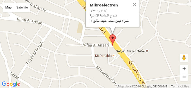
We are an online electronics store based in Jordan-Amman. The products we sell ranges from electronic products to modules and much more.
- AMMAN, Jordan. University Street, Khalifa Building 3rd floor
- Mobile: +962 7900 621 96, +962 65344772, +9627 8877 5522
- Phone: +962 6 5344772
- Fax: +96265344778
- Email: info@mikroelectron.com

2024 © Mikroelectron. ALL Rights Reserved. | Distributor Area
Made With By Tashfier.