Modbus RTU 4ch Relay 12v RS485 Module - 4 Input Optocoupler Isolation
Description:
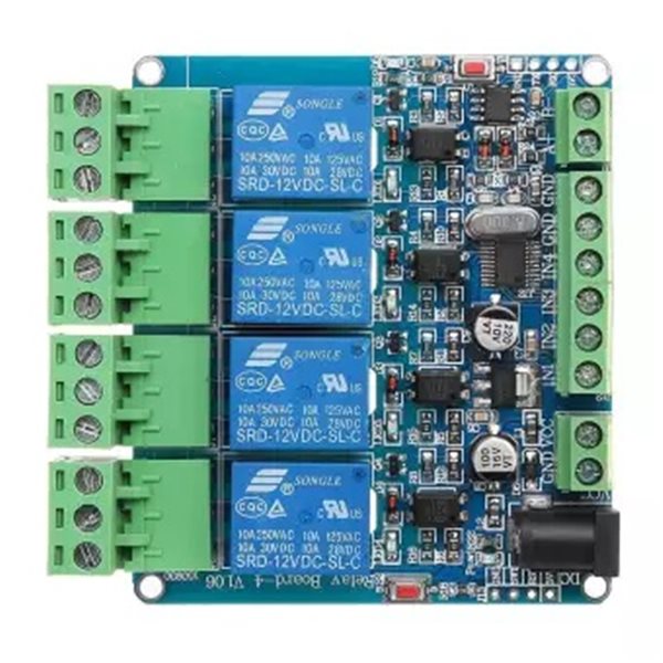
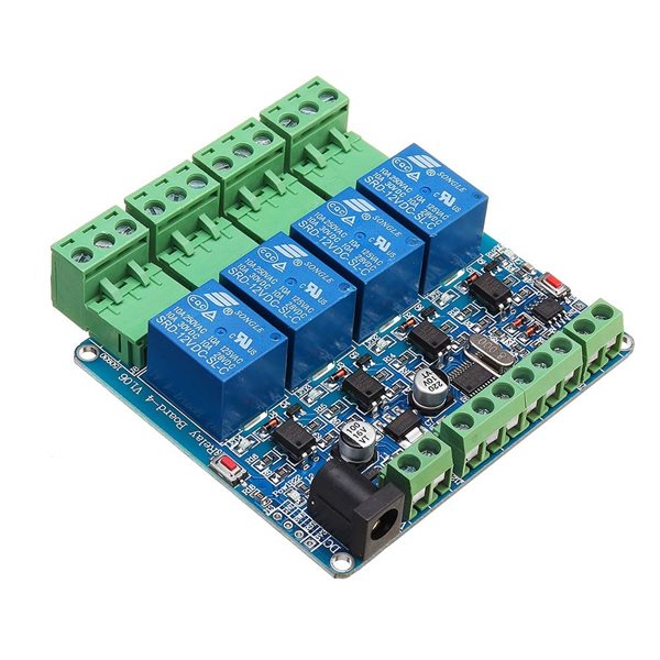
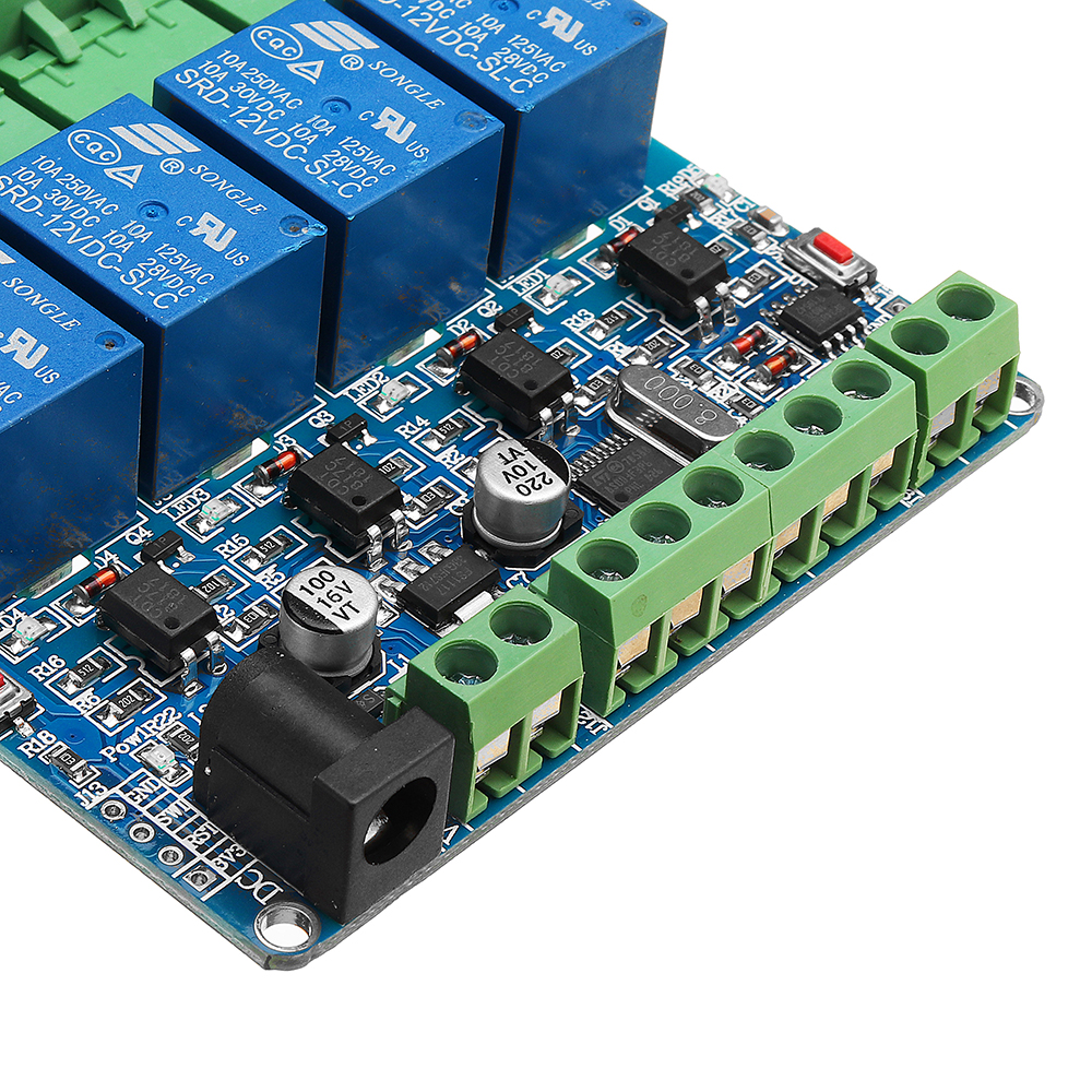
Modbus RTU 4 Channel Relay Module 4CH Input Optocoupler Isolation RS485 MCU For Arduino
Relay communication: multi-unit network 485 communication, based on MBDBUS-RTU protocol, the default communication address is 1, the user can modify the address by commandIN1 - IN4 are used by the switch. The status of the switch is read by 485, not by the input control relay output.
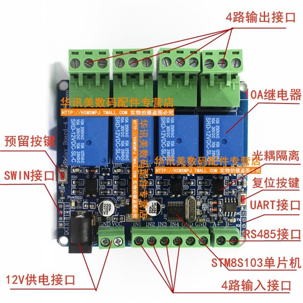
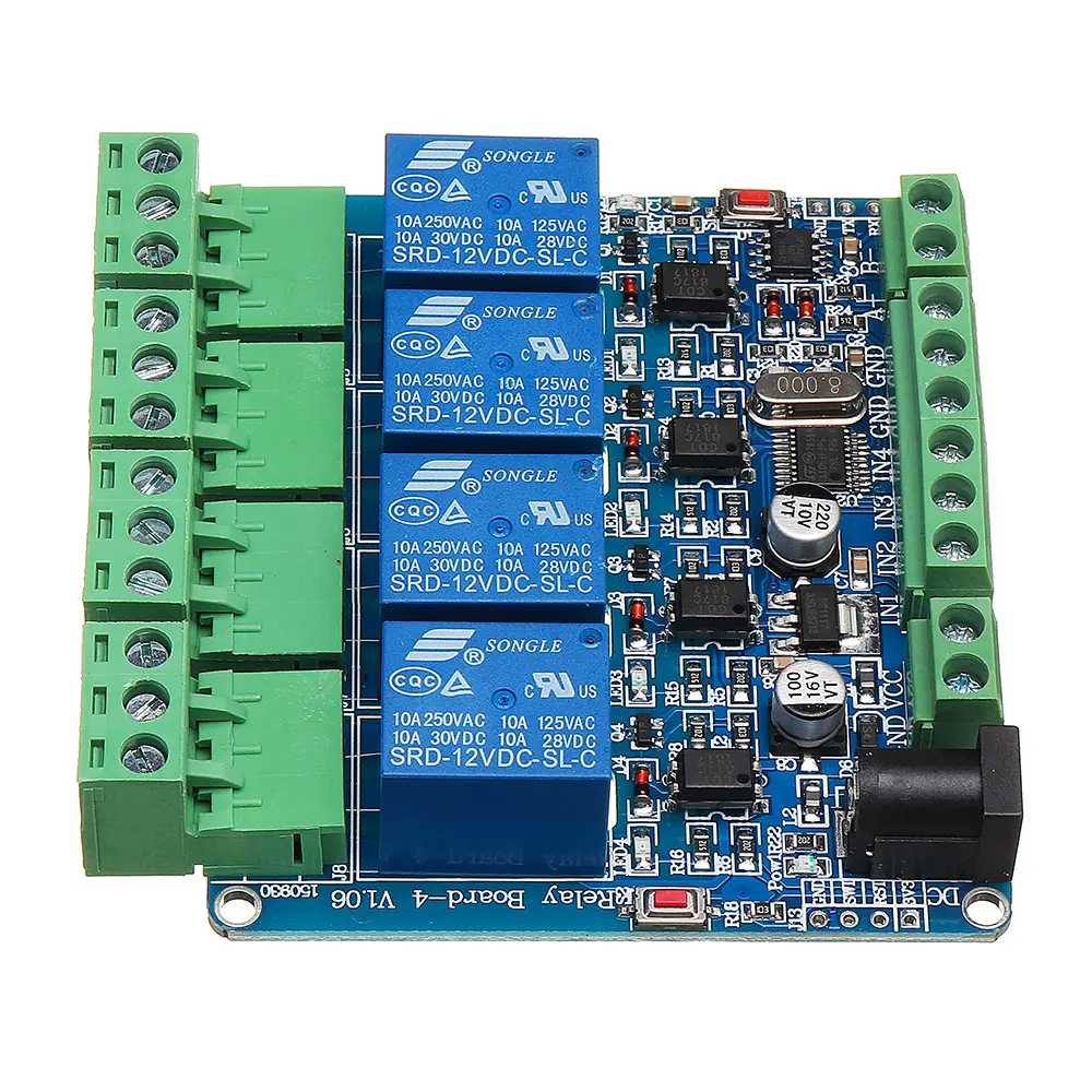
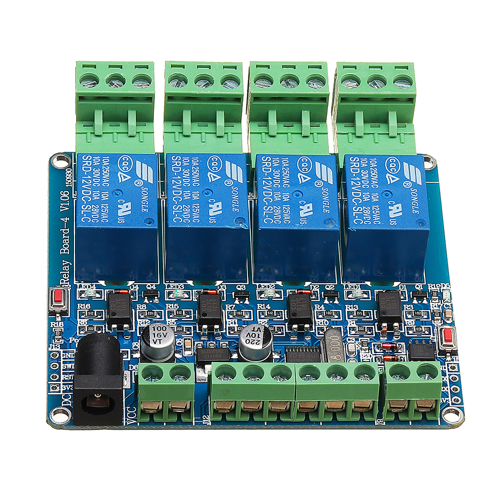
1. S1 reset button2. D5 running LED indicator
1. S1 reset button
2. D5 running LED indicator
Specifications:- 4 relays output
- STM8S103F3 Programmable Microcontroller
- 4 Optocoupler isolation
- 4 relay closed LED indicating lamp
- 4 group input connections
- 1 group RS485 communication connection.
- 1 power lights
- 1 user LED lamp
- Reset Key
- DC 12V Input Jack
- One SWIM download interface - (STLINK-V2 download)

Pin description:
1. LED connected to user LED
2. TX RX is connected to 485 port and pin TTL port
3. KEY user button (red button on the left)
4. EN 485 use end
5. IN1 -IN4 input port is directly connected to the terminal
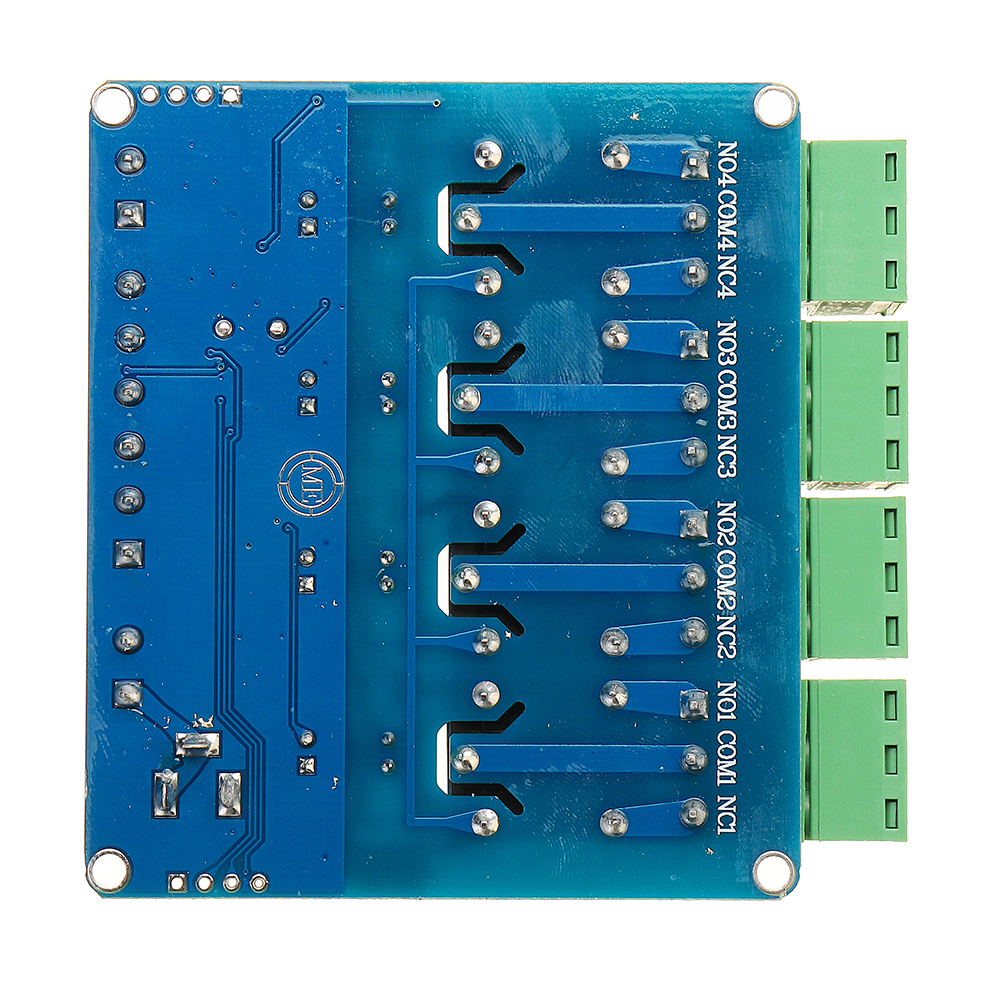
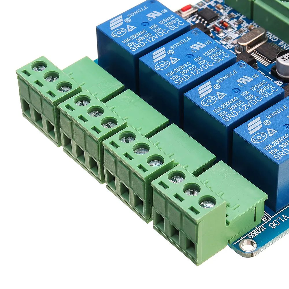
6. K1 - K4 relay output control
7. SWIM burning program J13
Modbus RTU command
Baud Rate: 9600 8 NONE 1
/ ************************************************* ****************** /
Setting address is: 01
00 06 40 00 00 01 5c 1b
Setting address is: 02
00 06 40 00 00 02 1c 1a
Read address
00 03 40 00 00 01 90 1b
/ ************************************************* ****************** /
Read the software version
00 03 00 04 00 01 c4 1a // [month] broadcast read (only by one device to address all practical, easy to test)
0,003,000,800,010,419 [years] // broadcast read (only by one device to address all practical, easy to test)
00 03 00 10 00 01 84 1e [when] // sub broadcast read (only by one device to address all practical, easy to test)
Read the hardware version (PCB version)
0,003,002,000,018,411 // broadcast read (only by one device to address all practical, easy to test)
/ ************************************************* ****************** /
[1 Address]
Open relay 1
01 05 00 01 01 00 9d 9a
Relay 1 closed
01 05 00 01 00 00 9c 0a
No. 2 relay open
01 05 00 02 01 00 6d 9a
No. 2 relay closed
01 05 00 02 00 00 6c 0a
3 relay open
01 05 00 03 01 00 3c 5a
3 Relay Off
01 05 00 03 00 00 3d ca
No. 4 relay open
01 05 00 04 01 00 8d 9b
4 Relay Off
01 05 00 04 00 00 8c 0b
Quanmie
01 05 00 ff 00 00 fd fa
All light
01 05 00 ff ff ff fc 4a
[2 Address]
Open relay 1
02 05 00 01 01 00 9d a9
Relay 1 closed
02 05 00 01 00 00 9c 39
No. 2 relay open
02 05 00 02 01 00 6d a9
No. 2 relay closed
02 05 00 02 00 00 6c 39
3 relay open
02 05 00 03 01 00 3c 69
3 Relay Off
02 05 00 03 00 00 3d f9
No. 4 relay open
02 05 00 04 01 00 8d a8
4 Relay Off
02 05 00 04 00 00 8c 38
Quanmie
02 05 00 ff 00 00 fd c9
All light
02 05 00 ff ff ff fc 79
/ ************************************************* ********************* /
No. 1 relay 1 channel status
01 01 00 01 00 04 6c 09
No. 1 Relay 2 channel status
01 01 00 02 00 04 9c 09
Relay 1 3 Channel status
01 01 00 03 00 04 CD C9
4 channel relay 1 status
01 01 00 04 00 04 7C 08
/ ************************************************* ******************** /
Read the status of all input interfaces
01 02 00 00 00 00 78 0a
Kit include:
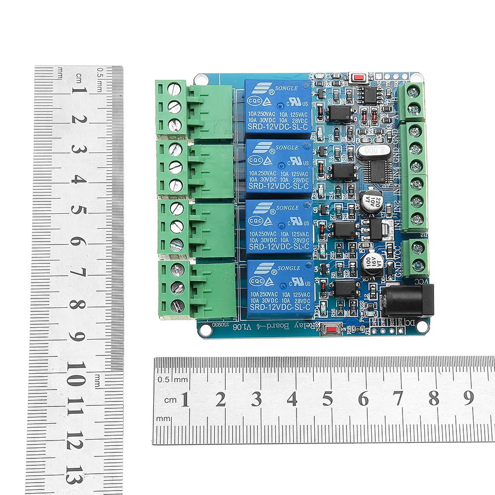
1 x Modbus RTU 4 channel Relay Module
Related Products
subscribe to our weekly newsletter


