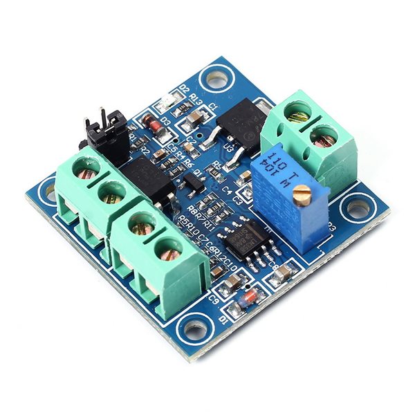
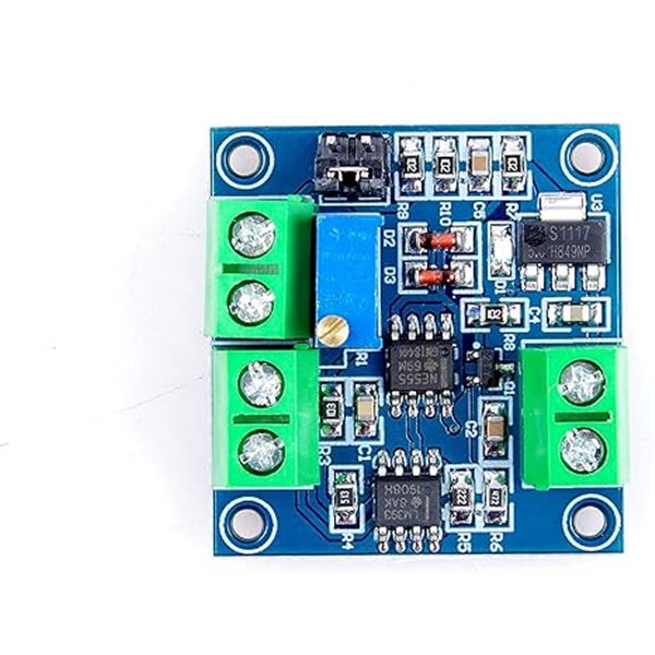
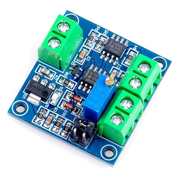
PWM to Voltage Module 0% -100% PWM Converted to 0-10V Voltage

Description:
After the electrical connection, there is no output signal, the output 0V, the input output only. The first time power on, it is best to do a calibration: Get a 50% duty cycle signal access to PWM, GND. Relative amplitude corresponding jumper. Frequency 1KHz ~ 3KHz, measured with a multimeter VOUT, GND two ports, then the table is displayed at 5V, adjust the potentiometer board, the display on the multimeter at 5.00V. This allows the calibration of the correspondence between the pulse signal and modules.
When the frequency is changed, the corresponding relationship may be offset needs to be recalibrated.
By adjusting the duty cycle to regulate the output voltage.
Accuracy can be controlled by adjusting potentiometer.
Features:
- Module Working voltage: DC12V ~ 30V; (Power Requirements: greater than 100mA).
- PWM signal receiving frequency range: 1KHz ~ 3KHz.
- 4.5V to 10V peak to peak level, jumper inserted at 5V. Class level signal mainly for general industrial control card (such as MACH3 board), 5V CPU interface;
- 10V to 24V peak to peak level, jumper inserted at 24V. Class level signal mainly for conventional PLC interface.
- Conversion range: 0% ~ 100% PWM converted to 0 ~ 10V voltage.
- Tolerance: 5%.
- Size:33*33*16mm(L*W*H).
- Weight:11g.
- Interface Description:
- VCC: Power supply 12V ~ 30V.
- GND: Power supply ground.
- PWM: PWM input signal positive.
- GND: the input signal negative terminal.
- VOUT: Output voltage 0 ~ 10V.
- GND: output voltage ground.
Related Products
subscribe to our weekly newsletter
We are an online electronics store based in Jordan-Amman. The products we sell ranges from electronic products to modules and much more.
- AMMAN, Jordan. University Street, Khalifa Building 3rd floor
- Mobile: +962 7900 621 96, +962 65344772, +9627 8877 5522
- Phone: +962 6 5344772
- Fax: +96265344778
- Email: info@mikroelectron.com

2024 © Mikroelectron. ALL Rights Reserved. | Distributor Area
Made With By Tashfier.