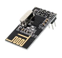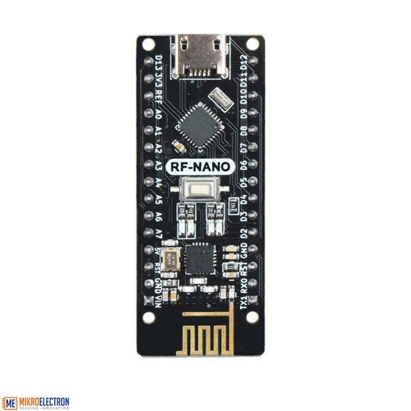
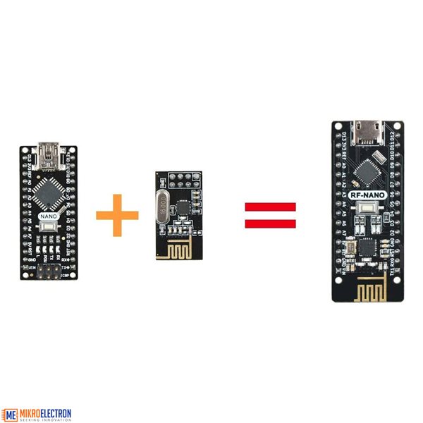
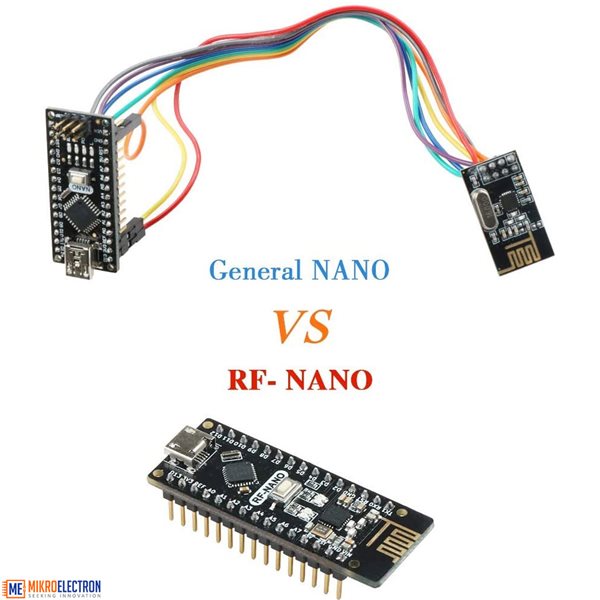
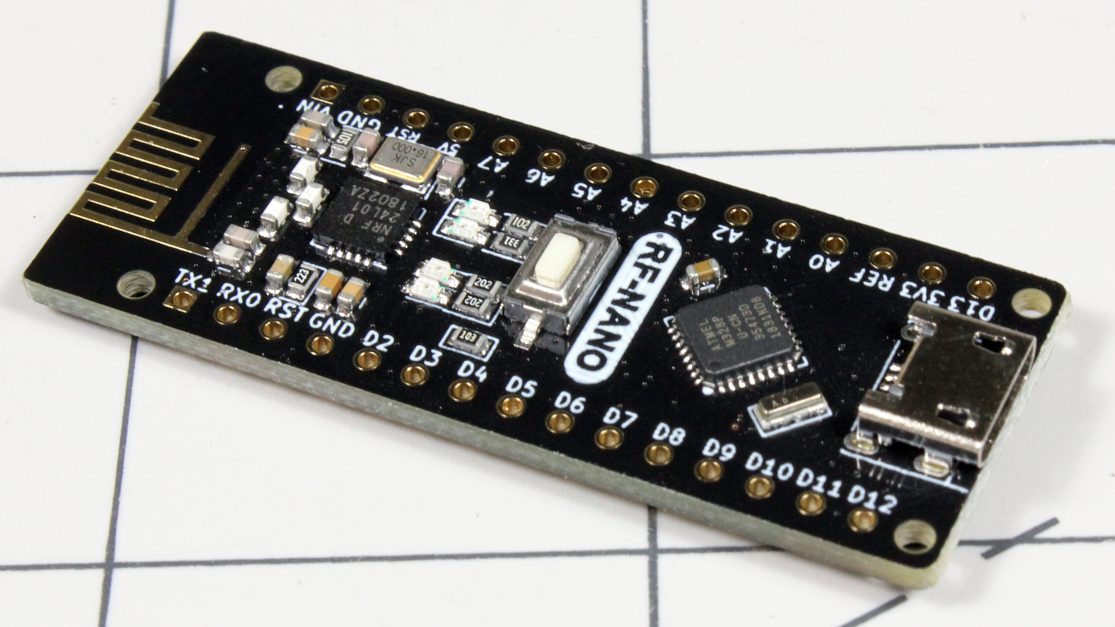
This board combines the NRF24L01+ wireless transceiver with the familiar form factor and programming paradigm of the Arduino Nano. For someone who needs wireless capabilities and prefers to keep solder and wiring work to a minimum, this appeared to be a wish come true. After a bit of yak shaving, it appears to fit the bill very well, and this article will help you avoid a couple possible pitfalls.
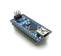
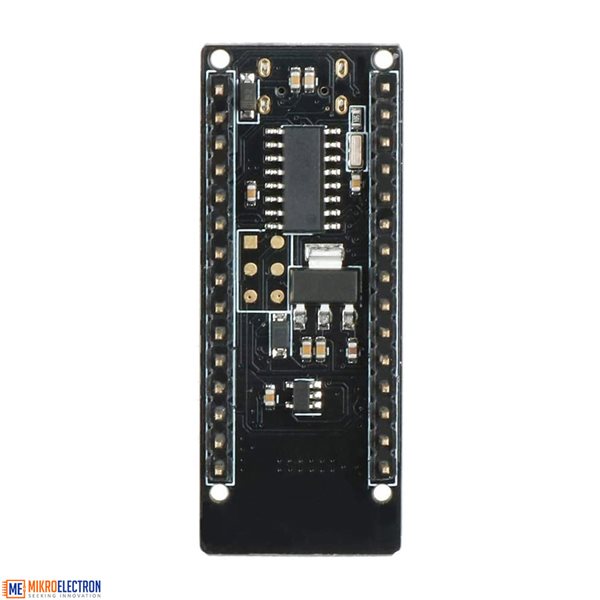
Hardware-wise, the board appears to be a fairly well-built Arduino Nano clone. It has the same footprint pins-wise, so you can use Nano shields, but it’s a bit longer to accommodate the NRF24L01+ and associated hardware. It also has a micro-USB connector, which is a nice change, since the mini-USB adapters used on the genuine article seem to become more and more rare as time goes by. When plugged in initially, however, my computer did not recognize it as…well, anything really.
Install Drivers
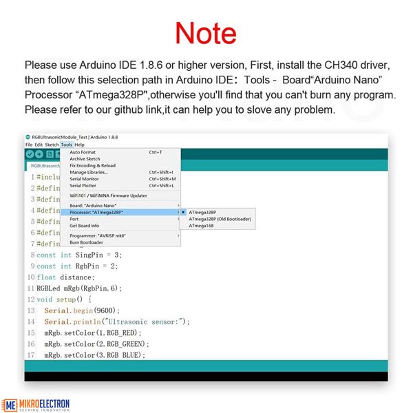
Fortunately, I’d browsed the reviews on the device, which indicated that a CH340 driver was needed. After searching, I found this page, and downloaded the Windows driver to use with my Windows 10 system. Mac and Linux instructions are also available if needed. After running the program and doing a restart, it recognized the RF-Nano without a problem.
Arduino IDE
With that done, I selected the proper port for the device, and selected “Arduino Nano” as the board. The processor was set as an ATmega328P—not the “ATmega328P (Old Bootloader)” option needed for some clones—and I was able to download the “Blink” example without issue. As expected, it then blinks on and off slowly with its built-in LED.
Communication
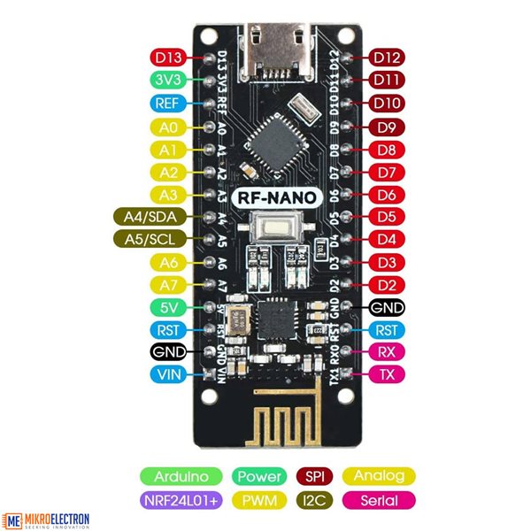
Documentation on these boards is fairly scant as of this writing, but from the PDF found here, the pins for the NRF24L01+ are configured as follows:
- CSN D9
- CE D10
- MOSI D11
- MISO D12
- SCK D13
Since wireless is already pre-configured into the RF-Nano board, you don’t have to worry about power or ground, and knowing communication pins should make it possible to use existing NRF libraries. The good news though is that getting started is even easier than that, and you can find the proper libraries, along with emitter and receiver examples here.
As arranged there, you’ll need to move a few directories around if you want a clean Arduino library with examples built-in, so I organized things a little differently in this repository. Just click “clone or download,” and save the zip file. Extract the “RF-Nano-master” directory, rename is to just “RF-Nano,” then place it into your Arduino library directory. In my case, this is located under Documents\Arduino\libraries.
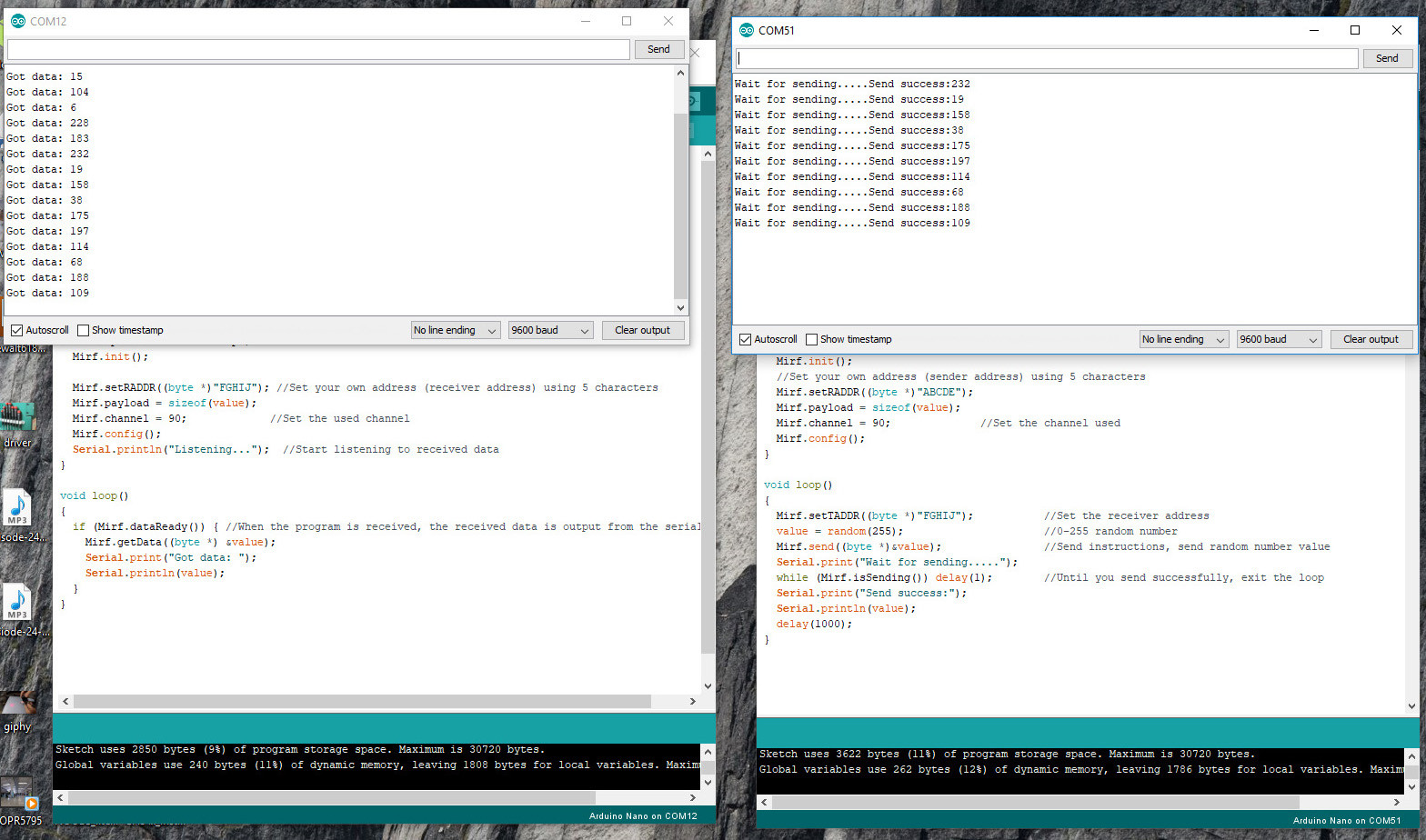
With the library in place, if you have two RF-Nano boards available, start two sessions of the Arduino IDE (directly from the shortcut, not via the File-New dialog), allowing you to use two serial ports simultaneously. Open up File > Examples > RF-Nano > Emitter in one window, and the Receive example code in the other. Upload the files to their corresponding RF-Nano, then open up a serial monitor on each IDE window to see one board transmitting random bytes to the other.