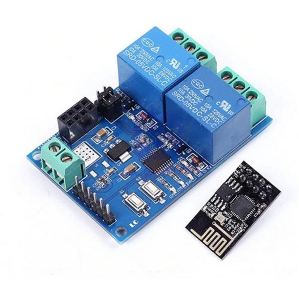
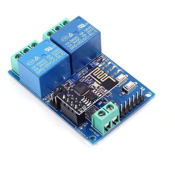
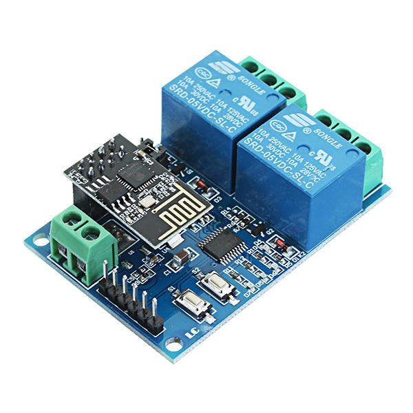
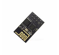
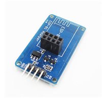
Relay Module DC 5V 2 CH Based ESP8266 ESP-01
Description:
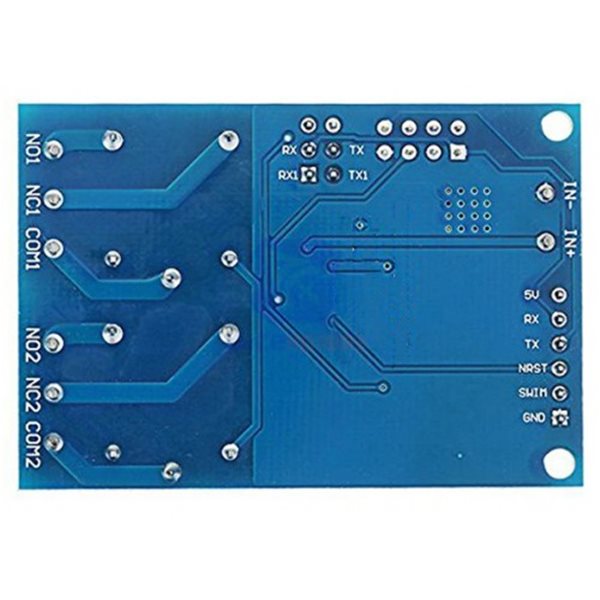
IN+, IN-: 5V power input
TX, RX: UART communication
SWIM, NRST: MCU program interface
S1: Mode selection key, default is mode 1
S2: Restore key
LED D2 and D4(red): Relay indicator
LED D7(red): Mode 1 indicator
LED D5(blue): Mode 2 indicator
LED D6(green): Working state indicator, the description of D6 as below:
(1)It’s means internal self-configuration or lost connection with the router when D6 off
(2)It’s means the ESP-01 are waiting for the APP configurate the password for it when D6 fast blink every 0.5S
(3)It’s means the whole configuration is done and waiting for establishing TCP connection with APP when D6 slow blink every 2S
(4) It’s means the TCP connection between ESP-01 and APP is OK when D6 on all the time.
Relay control command(must be hex format):
Open the first relay: A0 01 01 A2
Close the first Relay: A0 01 00 A1
Open the second relay: A0 02 01 A3
Close the second Relay: A0 02 00 A2
Kit include:
1 x 5V ESP8266 Dual WiFi Relay Module
Related Products
subscribe to our weekly newsletter


