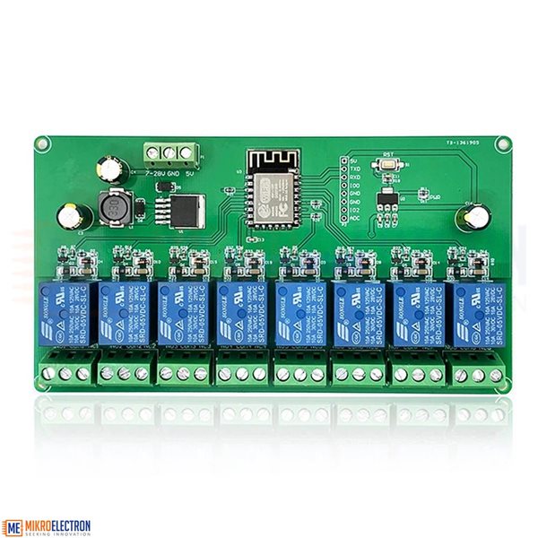
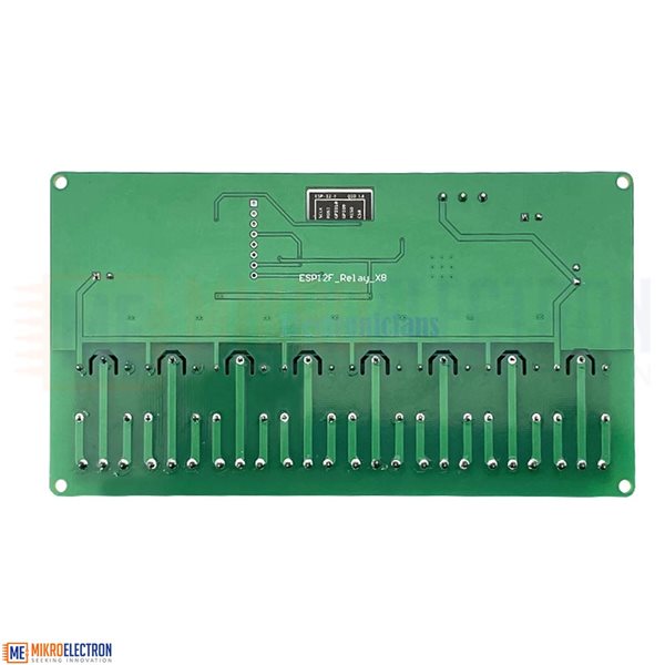
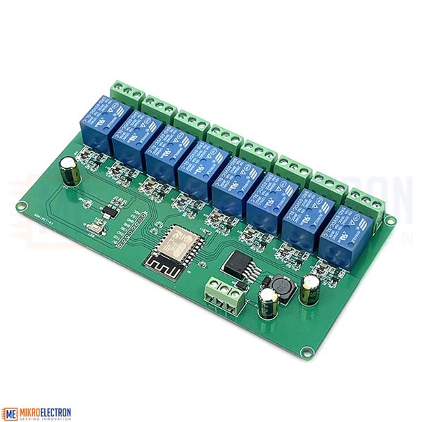
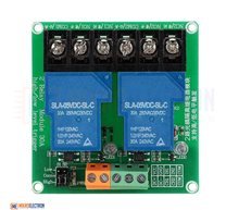
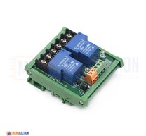
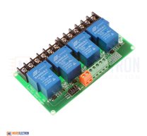
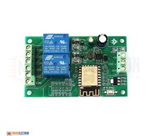
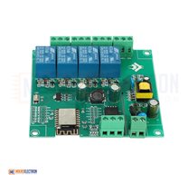
5V/7-28V ESP8266 WIFI 8 Channel Relay Wireless Module ( ESP12F_Relay_X8_v1.1 )
Description:
8 Channel Relay Module
Overview:
The ESP8266 eight-way relay development board is equipped with ESP-12F WiFi module and supports DC7-28V/5V power supply. Provide for Arduino development environment reference code, suitable for ESP8266 secondary development learning, smart home wireless control and other occasions.
Features:
1. On-board mature and stable ESP-12F Wi-Fi module, large capacity 4M Byte Flash.
2. The power supply mode supports DC7-28V/5V.
3. The onboard Wi-Fi module RST reset button.
4. ESP-12F supports the use of Eclipse/Arduino IDE and other development tools, and provides reference programs under for the Arduino development environment.
5. There are 8 5V relays on board, outputting switch signals, suitable for controlling loads whose working voltage is within AC 250V/DC30V.
6. Onboard power indicator and relay indicator.
GPIO #Component
GPIO00 Relay 7
GPIO01 User
GPIO02 Relay 8
GPIO03 Relay 6
GPIO04 User
GPIO05 User
GPIO09 User
GPIO10 User
GPIO12 Relay 3
GPIO13 Relay 2
GPIO14 Relay 4
GPIO15 Relay 1
GPIO16 Relay 5
GPIO17 User
OR
#define RELAYPIN_1 5
#define RELAYPIN_2 4
#define RELAYPIN_3 0
#define RELAYPIN_4 15
#define RELAYPIN_5 13
#define RELAYPIN_6 12
#define RELAYPIN_7 14
#define RELAYPIN_8 16
Note:
GPIO Pinout
This board has headers for every GPIO pin on its ESP-12F.
| Pin | Comment |
|---|---|
| 5V | Do not use 5V for programming |
| TX | Exposed on board 3.3V level! |
| RX | Exposed on board 3.3V level! |
| GPIO0 | 3.3V level! (pulled up, connect to GND for programming) |
| GND | |
| GND |
| Pin | Comment |
|---|---|
| 3V3 | For programming, inject 3.3V power here |
| 3V3 | For programming, inject 3.3V power here |
| 5V | |
| 5V | |
| GND | |
| GND | |
| GPIO5 | Relay 8 |
| GPIO4 | Relay 7 |
| GPIO0 | Relay 6 |
| GPIO2 | Exposed on board |
| GPIO15 | Relay 5 |
| GND |
| Pin | Comment |
|---|---|
| ADC | Exposed on board ( 0V-1V only ) |
| EN | Pulled up |
| GPIO16 | Relay 1 |
| GPIO14 | Relay 2 |
| GPIO12 | Relay 3 |
| GPIO13 | Relay 4 |
Kit include:
1 * 5V/7-28V ESP8266 WIFI 8 Channel Relay Module ESP-12F Development Board Power Supply Wireless WIFI Module
Documents:
Mikroelectron Code:
{"NAME":"ESP12F_Relay_X8_v1.1","GPIO":[230,1,231,229,1,1,1,1,226,225,227,224,228,1],"FLAG":0,"BASE":18}
Related Products
subscribe to our weekly newsletter


