8 Seven Segment LED Display with Keys and LEDs using TM1638
Description:
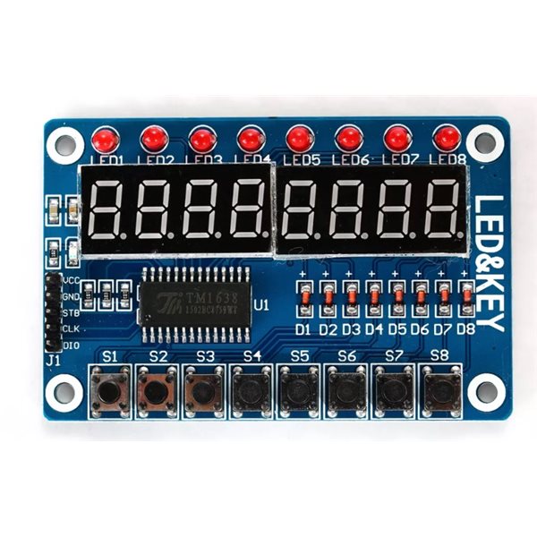
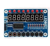
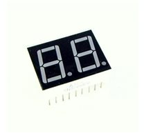
At long last I set out to work on one of my Arduino projects when I realized that I didn’t have any 4-digit 7 segment LED display at home. Since it was quite important part of the project I went to ebay and started looking for something when I found this:
This is an “8-Bit LED 8-Bit Digital Tube 8-Bit Key TM1638”. It seemed to be a very good fit for my project since it not only had the display but it also had some buttons – something I needed too. In addition it had only three control lines which would simplify things a lot by sparing me from dealing with shift registers on my own – something I would have to do had I used the cheapest 7 segment LED display. When I got the board I got baffled a little bit. It was just a piece of hardware without any documentation. I deciphered the symbol on the chip and went for a quest to find some information about how it worked. I found a data sheet but it was mostly in Chinese. Unfortunately 我的中文不好, so I only skimmed it and continued looking. I quickly found that there is a library I could use. However I did want to learn how the thing I bought actually worked, so I spent some time more time looking for more information about the board. Finally, I found this page which turned out to be the most helpful and allowed me to start experimenting.
As I already mentioned the board has just 3 control pins plus power and ground. The control pins are strobe, clock and data. The strobe and clock pins are only OUTPUT while the data pin can be both OUTPUT and INPUT. The strobe pin is used when sending data to the board – you set thestrobe pin to LOW before you start sending data – one or more bytes – and then set the strobe pin back to HIGH. Note that there is just one data pin which means the data is being sent 1 bit at a time. This is where the clock pin comes into play. When sending data you set the clock pin to LOWthen you set the data pin and set the clock pin back to HIGH to commit the bit value. You are probably already familiar with this pattern (if not take a look at this post) – it is the standard way of sending data with shift registers and therefore we can just use the standard shiftOut function to send 8 bits of data with just one line of code.
The data sent to the board follow a protocol where the first byte tells the board what we want to do (I call it ‘command’) and is followed by zero or more bytes that are arguments for the selected function. Arguments are sent separately (i.e. the strobe pin needs to be set to HIGH after sending the command and again to LOW before sending arguments). The board has 4 functions:
- activate/deactivate board and initialize display
- write a byte at specific address
- write bytes starting from specific address
- read buttons
To activate the board and set the display brightness we use the 1000abbb (0x8?) command where the bit marked as a is used to activate/deactivate the board and bits marked as bbb are used to set the brightness of the display. For example to activate the board and set the brightness of the display to the maximum value we need to send 0x8f. This function does not have any arguments.
To write a byte at specific address we send the 010000100 (0x44) command followed by the address in the form of 1100aaaa (aaaa bits denote the location we want to write to) followed by the value. For example to write the value 0x45 at address 0x0a we would have to send the following sequence of bytes: 0x44 0xca 0x45.
If we want to write values at consecutive addresses (very helpful to reset the board) we would send01000000 (0x40) followed by the starting address (again in the form of 1100aaaa) followed by the values we want to write. For instance if we send 0x40 0xc0 0x00 0x01 0x02 0 would be written at address 0, 1 would be written at address 1 and 2 would be written at address 2. Note that we have 4 bits to select the address which means there are sixteen locations that can be written to. If you continue writing after reaching the address 0x0f it will wrap and you will start again from address0x00.
To read buttons we send the 010000010 (0x42) command, set the data pin as INPUT and read 4 bytes containing button status.
| Command | Arguments | Description |
|---|---|---|
0x8? (1000abbb) | (none) | activate board (bit a), set brightness (bits b) |
0x44 (01000100) | 0xc? 0x?? | write value 0x?? at location 0xc?(single address mode) |
0x40 (01000000) | 0xc? 0x?? 0x?? 0x?? | write values 0x?? starting from location 0xc? (address auto increment mode) |
0x42 (01000010) | N/A | read buttons |
Now we know we can write values to one of the 16 locations. This is the way we turn LEDs on and control the display. The board has two 4 digit 7 segment LEDs displays and 8 LEDs. Each of them has a dedicated address to which a value needs to be written to control the corresponding item. For instance if to turn on the first LED we would write 1 at address 0x01. Below is a list of locations with short explanations.
| Address | Description |
|---|---|
| 0x00 (0000) | display #1 |
| 0x01 (0001) | LED #1 00000001 – red, 00000010 – green |
| 0x02 (0010) | display #2 |
| 0x03 (0011) | LED #2 00000001 – red, 00000010 – green |
| 0x04 (0100) | display #3 |
| 0x05 (0101) | LED #3 00000001 – red, 00000010 – green |
| 0x06 (0110) | display #4 |
| 0x07 (0111) | LED #4 00000001 – red, 00000010 – green |
| 0x08 (1000) | display #5 |
| 0x09 (2001) | LED #5 00000001 – red, 00000010 – green |
| 0x0a (1010) | display #6 |
| 0x0b (1011) | LED #6 00000001 – red, 00000010 – green |
| 0x0c (1100) | display #7 |
| 0x0d (1101) | LED #7 00000001 – red, 00000010 – green |
| 0x0e (1110) | display #8 |
| 0x0f (1111) | LED #8 00000001 – red, 00000010 – green |
(You might have noticed that according to the chart LEDs can be either red or green. I am cheap so I got the cheapest board I could find on ebay and it turned out it had only red LEDs so I was not able to test the green color.)
We now have all the information needed to breathe some life into the board. First we need to connect the TM1638 based board to our Arduino board. This is how I did it:
Arduino              TM1638 based board
3.3V   ------------------ VCC
GND    ------------------ GND
PIN #7 ------------------ STB
PIN #8 ------------------ DIO
PIN #9 ------------------ CLK
The setup function needs to activate and reset the board. For readability I created a helper function for sending commands and a separate function for setup. Here is how the code to setup the board looks like:
1 2 3 4 5 6 7 8 9 10 11 12 13 14 15 16 17 18 19 20 21 22 23 24 25 26 27 28 29 30 31 32 | const int strobe = 7;const int clock = 9;const int data = 8;void sendCommand(uint8_t value){ digitalWrite(strobe, LOW); shiftOut(data, clock, LSBFIRST, value); digitalWrite(strobe, HIGH);}void reset(){ sendCommand(0x40); // set auto increment mode digitalWrite(strobe, LOW); shiftOut(data, clock, LSBFIRST, 0xc0); // set starting address to 0 for(uint8_t i = 0; i < 16; i++) { shiftOut(data, clock, LSBFIRST, 0x00); } digitalWrite(strobe, HIGH);}void setup(){ pinMode(strobe, OUTPUT); pinMode(clock, OUTPUT); pinMode(data, OUTPUT); sendCommand(0x8f); // activate and set brightness to max reset();} |
Here is how this works. The code starts executing from the setup function. First we set pins 7, 8, 9 as output pins. Next we activate the board and set the brightness to the maximum value by sending0x8f. Finally we reset the board by clearing all the memory locations. We do it by setting the board to the address auto increment mode (0x40), selecting 0 as the starting address (0xc0) and sending0 sixteen times. Now that the board is ready to work with let’s display something. An easy thing to display will be 8. in the first and last digit position on the display and light the 3rd and 6th LED. To do that we will use the single address mode since the locations we are going to write to are not consecutive. Our loop function that does this looks as follows:
1 2 3 4 5 6 7 8 9 10 11 12 13 14 15 16 17 18 19 20 21 22 23 24 | void loop(){ sendCommand(0x44); // set single address digitalWrite(strobe, LOW); shiftOut(data, clock, LSBFIRST, 0xc0); // 1st digit shiftOut(data, clock, LSBFIRST, 0xff); digitalWrite(strobe, HIGH); digitalWrite(strobe, LOW); shiftOut(data, clock, LSBFIRST, 0xc5); // 3rd LED shiftOut(data, clock, LSBFIRST, 0x01); digitalWrite(strobe, HIGH); digitalWrite(strobe, LOW); shiftOut(data, clock, LSBFIRST, 0xcb); // 3rd LED shiftOut(data, clock, LSBFIRST, 0x01); digitalWrite(strobe, HIGH); digitalWrite(strobe, LOW); shiftOut(data, clock, LSBFIRST, 0xce); // last digit shiftOut(data, clock, LSBFIRST, 0xff); digitalWrite(strobe, HIGH);} |
You can find the entire sample in the repo on github.
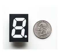
Displaying 8. is cool but it would be even cooler if we knew the relation between the value sent to the board and what will be shown. The board is using the standard 7 segment coding, so the value sent to the board is a byte with bits coded as follows: [DP]GFEDCBA. Each bit will light one segment as per the image below:
So, for instance if you wanted to display A you would have to write 0x77 at the corresponding location.
Now we know how to control LEDs and the display. But there is one more thing the board offers – buttons. Reading what buttons are depressed works a little bit different from what we have seen so far. First we need to send the 0x42 command, then we set the data pin as an input pin. Finally we need to read 4 bytes from the board (bit by bit). The first byte contains status for buttons S1 (bit 1) and S5 (bit 4), the second byte contains status for buttons S2 (bit 2) and S6 (bit 5) and so on. If we| (i.e. logical `or`) all the bytes we will end up having a byte where each bit corresponds to one button – if a bit set to one means that the corresponding button is depressed. Here is a little program (I omitted the setup – it is identical as in the first sample) where the board will light an LED over a button that is pressed.
1 2 3 4 5 6 7 8 9 10 11 12 13 14 15 16 17 18 19 20 21 22 23 24 25 26 27 28 29 30 31 32 33 34 35 36 37 38 39 40 41 | uint8_t readButtons(void){ uint8_t buttons = 0; digitalWrite(strobe, LOW); shiftOut(data, clock, LSBFIRST, 0x42); pinMode(data, INPUT); for (uint8_t i = 0; i < 4; i++) { uint8_t v = shiftIn(data, clock, LSBFIRST) << i; buttons |= v; } pinMode(data, OUTPUT); digitalWrite(strobe, HIGH); return buttons;}void setLed(uint8_t value, uint8_t position){ pinMode(data, OUTPUT); sendCommand(0x44); digitalWrite(strobe, LOW); shiftOut(data, clock, LSBFIRST, 0xC1 + (position << 1)); shiftOut(data, clock, LSBFIRST, value); digitalWrite(strobe, HIGH);}void loop(){ uint8_t buttons = readButtons(); for(uint8_t position = 0; position < 8; position++) { uint8_t mask = 0x1 << position; setLed(buttons & mask ? 1 : 0, position); }} |
Again, you can find the entire example in my github repo.
These are the basic building blocks and you use them to build something more useful. Here is a video of a little demo project I built:
The code for this demo is also on github.
Note:
Mikroelectron Code:
const int strobe = 7; const int clock = 9; | |
| const int data = 8; | |
| void sendCommand(uint8_t value) | |
| { | |
| digitalWrite(strobe, LOW); | |
| shiftOut(data, clock, LSBFIRST, value); | |
| digitalWrite(strobe, HIGH); | |
| } | |
| void reset() | |
| { | |
| sendCommand(0x40); // set auto increment mode | |
| digitalWrite(strobe, LOW); | |
| shiftOut(data, clock, LSBFIRST, 0xc0); // set starting address to 0 | |
| for(uint8_t i = 0; i < 16; i++) | |
| { | |
| shiftOut(data, clock, LSBFIRST, 0x00); | |
| } | |
| digitalWrite(strobe, HIGH); | |
| } | |
| void setup() | |
| { | |
| pinMode(strobe, OUTPUT); | |
| pinMode(clock, OUTPUT); | |
| pinMode(data, OUTPUT); | |
| sendCommand(0x8f); // activate | |
| reset(); | |
| } | |
| uint8_t readButtons(void) | |
| { | |
| uint8_t buttons = 0; | |
| digitalWrite(strobe, LOW); | |
| shiftOut(data, clock, LSBFIRST, 0x42); | |
| pinMode(data, INPUT); | |
| for (uint8_t i = 0; i < 4; i++) | |
| { | |
| uint8_t v = shiftIn(data, clock, LSBFIRST) << i; | |
| buttons |= v; | |
| } | |
| pinMode(data, OUTPUT); | |
| digitalWrite(strobe, HIGH); | |
| return buttons; | |
| } | |
| void setLed(uint8_t value, uint8_t position) | |
| { | |
| pinMode(data, OUTPUT); | |
| sendCommand(0x44); | |
| digitalWrite(strobe, LOW); | |
| shiftOut(data, clock, LSBFIRST, 0xC1 + (position << 1)); | |
| shiftOut(data, clock, LSBFIRST, value); | |
| digitalWrite(strobe, HIGH); | |
| } | |
| void loop() | |
| { | |
| uint8_t buttons = readButtons(); | |
| for(uint8_t position = 0; position < 8; position++) | |
| { | |
| uint8_t mask = 0x1 << position; | |
| setLed(buttons & mask ? 1 : 0, position); | |
| } | |
| } |
Related Products

subscribe to our weekly newsletter
We are an online electronics store based in Jordan-Amman. The products we sell ranges from electronic products to modules and much more.
- AMMAN, Jordan. University Street, Khalifa Building 3rd floor
- Mobile: +962 7900 621 96, +962 65344772, +9627 8877 5522
- Phone: +962 6 5344772
- Fax: +96265344778
- Email: info@mikroelectron.com

2024 © Mikroelectron. ALL Rights Reserved. | Distributor Area
Made With By Tashfier.