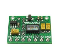
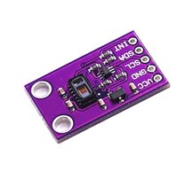
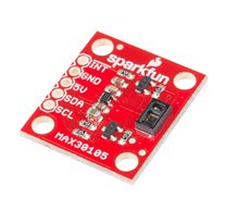
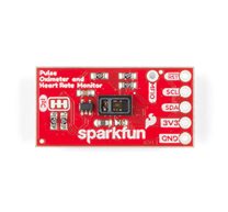
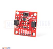
MAX30102 Heartbeat Frequency Tester Heart Rate Sensor Module pulse Detection Blood Oxygen Concentration
Description:
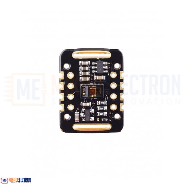
The MAX30102 module uses a red LED (660nm), infrared LED (880nm), and photodetector to approximate blood oxygen content and heart rate pulses. The sensor can be placed on a finger, wrist, or other area with significant blood flow to measure these parameters.
The Main Parameters:
LED peak wavelength: 660nm/880nm
LED power supply voltage: 3.3~5V
Detection signal type: light reflection signal (PPG)
Output signal interface : I2C interface
Communication interface voltage: 1.8~3.3V~5V (optional)
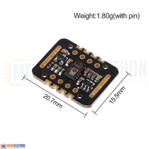
Board reserved assembly hole size: 0.5 x 8.5mm
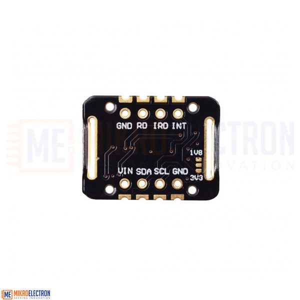
Pin Description:
VIN: main power input terminal 1.8-5V
3-bit pad: Select the pull-up level of the bus, depending on the pin master voltage, select 1.8v or 3_3v (this terminal contains 3.3V and above)
SCL: the clock connected to the I2C bus;
SDA: data connected to the I2C bus;
INT: Interrupt pin of the MAX30102 chip;
RD: RED LED ground terminal of MAX30102 chip, generally not connected;
IRD: The IR LED ground of the MAX30102 chip is generally not connected;
GND: Ground wire.
Principle Description:
Light-dissolving method: measuring the pulse and blood oxygen saturation by using human tissue to cause different transmittance when the blood vessel beats;
Light source: a specific wavelength of light-emitting diode selective for oxyhemoglobin (H bO 2 ) and hemoglobin ( Hb ) in arterial blood;
The transmittance is converted into an electrical signal: the change in the volume of the arterial pulsation causes a change in the transmittance of the light. At this time, the
photoelectric variation receives the reflected light from the human tissue, converts it into an electrical signal, and amplifies and outputs it.
Kit include:
1 x Heart Rate Sensor Module MAX30102
1 x Sets of Pin Header
Documents:
Related Products
subscribe to our weekly newsletter
We are an online electronics store based in Jordan-Amman. The products we sell ranges from electronic products to modules and much more.
- AMMAN, Jordan. University Street, Khalifa Building 3rd floor
- Mobile: +962 7900 621 96, +962 65344772, +9627 8877 5522
- Phone: +962 6 5344772
- Fax: +96265344778
- Email: info@mikroelectron.com

2024 © Mikroelectron. ALL Rights Reserved. | Distributor Area
Made With By Tashfier.