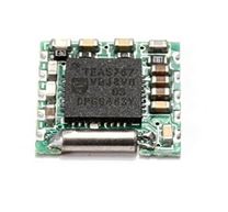
TEA5767 FM Radio Module
Description:
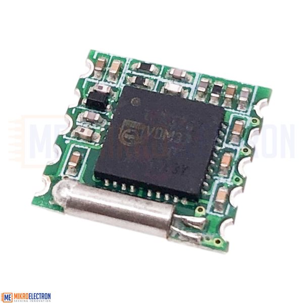
The TEA5767 Module is a single-chip FM Radio IC circuit designed for low-voltage applications, making it ideal for use in embedded systems and microcontroller platforms like Arduino and other 3.3V development boards. This versatile chip includes intermediate frequency selectivity and an integrated FM demodulator. Its ease of interfacing compatibility with the I2C communication protocol makes it straightforward to connect to other development boards. With minimal additional components, it can function as a stand-alone radio receiver. The TEA5767 supports a frequency range of 88MHz to 108MHz, allowing it to tune into FM stations in India, Japan, Europe, and the United States.
Specifications:
- Operating voltage: 3.3V
- Interface: I2C using SDA & SCL pins
- High sensitivity with a low-noise input amplifier.
- RF AGC (Automatic Gain Control) for signal optimization.
- Standby Mode and Soft Mute for power-saving and audio control.
- Stereo decoding without manual adjustments.
- Precise tuning using a Phase Locked Loop synthesizer.
- Integrated FM IF selectivity and LC Tuner Oscillator with low-cost chip inductors.
- Complete FM demodulator for seamless signal processing.
- Crystal reference frequency oscillator for accuracy.
- I2C interface for easy integration.
- Supports a frequency range of 76MHz to 108MHz, covering various FM stations.
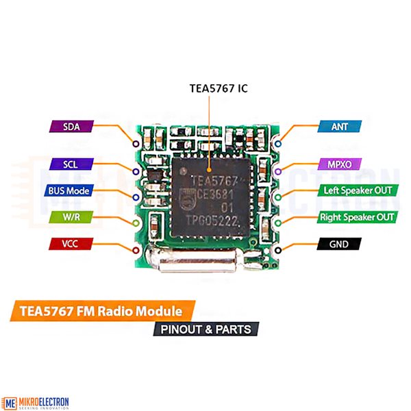
Pinout & Parts Description of TEA5767 FM radio Module:
There are a total of 10 pins on this module:
TEA5767 FM Radio Module Pinout:
- SCL (Serial Clock): This is the clock pin for I2C communication. Connect it to the SCL pin on your Arduino or microcontroller.
- SDA (Serial Data): This is the data pin for I2C communication. Connect it to the SDA pin on your Arduino or microcontroller.
- BUS or MODE: This pin selects the communication mode (I2C or Serial). Connect it to ground (GND) for I2C mode, or leave it unconnected for Serial mode.
- W/R (Write/Read): This pin determines whether you are writing data to the module or reading data from it. Connect it to ground (GND) for write mode or leave it unconnected for read mode.
- VCC (Voltage Supply): Connect this pin to the power supply voltage (typically 3.3V or 5V, depending on the module's specifications).
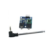
- ANT (Antenna): Connect an external FM antenna to this pin for better reception. If you don't have an FM antenna, you can use a simple wire as an antenna.
- MPXO (Multiplex Output): This pin provides the demodulated audio output signal. Connect it to an audio amplifier or speaker for audio output.
- Left & Right Out (L & R Out): This pin provides the audio signal for the left as well as Right audio channel when the TEA5767 module is operating in stereo mode. Connect it to the input of an audio amplifier or speaker circuit for the left channel.
- GND (Ground): Connect this pin to the ground (GND) of your power supply or microcontroller.
Kit include:
1 x TEA5767 FM Radio Module
Related Products

subscribe to our weekly newsletter
We are an online electronics store based in Jordan-Amman. The products we sell ranges from electronic products to modules and much more.
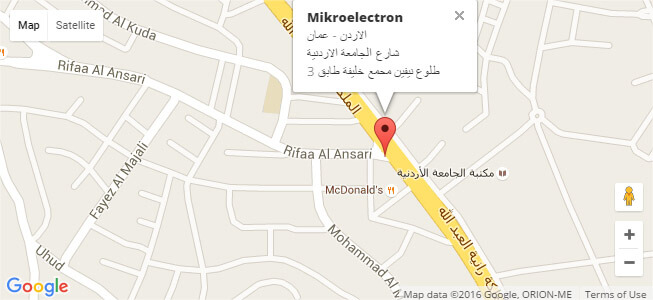
- AMMAN, Jordan. University Street, Khalifa Building 3rd floor
- Mobile: +962 7900 621 96, +962 65344772, +9627 8877 5522
- Phone: +962 6 5344772
- Fax: +96265344778
- Email: info@mikroelectron.com

2024 © Mikroelectron. ALL Rights Reserved. | Distributor Area
Made With By Tashfier.