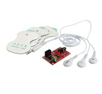
Finger heart rate sensor
Description:
The Easy Pulse sensor is based on the principle of photoplethysmography (PPG) which is a non-invasive method of measuring the variation in blood volume in tissues using a light source and a detector. Since the change in blood volume is synchronous to the heart beatthis technique can be used to calculate the heart rate. Transmittance and reflectance are two basic types of photoplethysmography. For the transmittance PPGa light source is emitted in to the tissue and a light detector is placed in the opposite side of the tissue to measure the resultant light. Because of the limited penetration depth of the light through organ tissuethe transmittance PPG is applicable to a restricted body partsuch as the finger or the ear lobe. Howeverin the reflectance PPGthe light source and the light detector are both placed on the same side of a body part. The light is emitted into the tissue and the reflected light is measured by the detector. As the light doesn’t have to penetrate the bodythe reflectance PPG can be applied to any parts of human body. In either casethe detected light reflected from or transmitted through the body part will fluctuate according to the pulsatile blood flow caused by the beating of the heart.
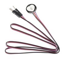
The original Easy Pulse design was based on the reflectance approach and used TCRT1000 IR device as sensor. It could detect the pulse signal when an user places his/her fingertip on the top of the sensor. While this sensor performed wellit was susceptible to a very small movement of the finger. Sothe user should keep the finger very steady to obtain the accurate pulse signal. Easy Pulse Version 1.1 uses a more robust sensor (HRM-2155E) that operates in transmission mode and fits tight around the fingertipthereby it is less prone to motion.
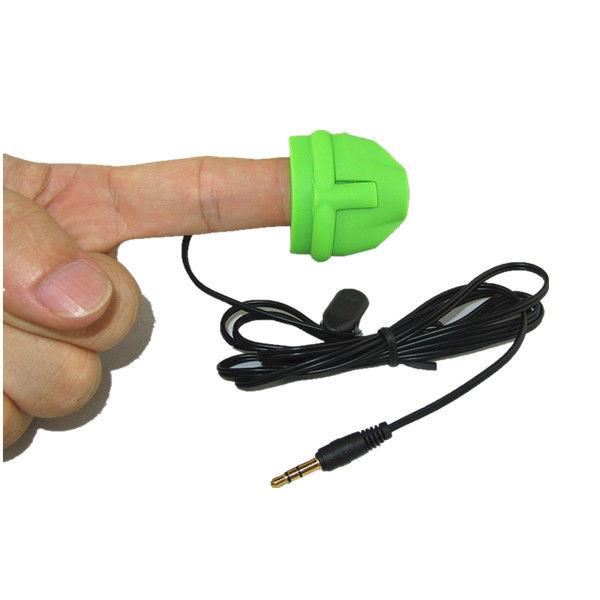
The HRM-2511E sensor is manufactured by Kyoto Electronic Co.Chinaand operates in transmission mode. The sensor body is built with flexible Silicone rubber material that helps to keep the sensor tightly hold to the finger. Inside the sensor casean IR LED and a photodetector are placed on two opposite sides and are facing each other. When a fingertip is plugged into the sensorit is illuminated by the IR light coming from the LED. The photodetector diode receives the transmitted light through the tissue on other side. More or less light is transmitted depending on the tissue blood volume. Consequentlythe transmitted light intensity varies with the pulsing of the blood with heart beat. A plot for this variation against time is referred to be a photoplethysmographic or PPG signal. The following picture shows a basic transmittance PPG probe setup to extract the pulse signal from the fingertip.

HRM-2511E as a transmission PPG probe
The PPG signal consists of a large DC componentwhich is attributed to the total blood volume of the examined tissueand a pulsatile (AC) componentwhich is synchronous to the pumping action of the heart. The AC componentwhich carries vital information including the heart rateis much smaller in magnitude than the DC component. A typical PPG waveform is shown in the figure below (not to scale).

PPG components shown not to scale
The two maxima observed in the PPG are called Sytolic and Diastolic peaksand they can provide valuable information about the cardiovascular system (this topic is outside the scope of this article). The time duration between two consecutive Systolic peaks gives the instantaneous heart rate.
Here are the features of Easy Pulse V1.1 sensor module.
- Uses HRM-2511E transmission PPG sensor for stable readings
- MCP6004 Opamp with rail-to-rail output capability for maximum signal swing
- Separate analog and digital outputs
- Potentiometer gain control for the analog output
- Pulse width control for the digital output
- Additional test points on board for analyzing signals at different stages of instrumentation
Circuit diagrams
The following circuit shows the ON/OFF control scheme for the infra-red light source inside HRM-2511E. Note that the Enable signal must be pulled high in order to turn on the IR LED. The photodetector output (VSENSOR) contains the PPG signal that goes to a two-stage filter and amplifier circuit for further processing.

HRM-2511E pulse sensor circuit
The PPG signal coming from the photodetector is weak and noisy. So we need an amplifier and filter circuits to boost and clean the signal. In Stage I instrumentationthe signal is first passed through a passive (RC) high-pass filter (HPF) to block the DC component of the PPG signal. The cut-off frequency of the HPF is 0.5Hzand is set by the values of R (=68K) and C (=4.7uF). The output from the HPF goes to an Opamp-based active low-pass filter (LPF). The Opamp operates in non-inverting mode and has gain and cut-off frequency set to 48 and 3.4Hzrespectively. In order to achieve a full swing of the PPG signal at the outputthe negative input of the Opamp is tied to a reference voltage (Vref) of 2.0V. The Vref is generated using a zener diode. At the output is a potentiometer (P1) that acts as a manual gain control. The output from the active LPF now goes to Stage II instrumentation circuitwhich is basically a replica of the Stage I circuit. Note that the amplitude of the signal going to the second stage is controlled by P1. The Opamp used in this project is MCP6004 from Microchipwhich is a Quad-Opamp device and provides rail-to-rail output swing.

Stage I filtering and amplification
The second stage also consists similar HPF and LPF circuits. The two-step amplified and filtered signal is now fed to a third Opampwhich is configured as a non-inverting buffer with unity gain. The output of the buffer provides the required analog PPG signal. The potentiometer P1 can be used to control the amplitude of the PPG signal appearing at the output of the buffer stage.

Stage II instrumentation circuit
The fourth Opamp inside the MCP6004 device is used as a voltage comparator. The analog PPG signal is fed to the positive input and the negative input is tied to a reference voltage (VR). The magnitude of VR can be set anywhere between 0 and Vcc through potentiometer P2 (shown below). Every time the PPG pulse wave exceeds the threshold VRthe output of the comparator goes high. Thusthis arrangement provides an output digital pulse synchronous to heart beat. Note that the width of the pulse is also determined by VR. An LED connected to the digital output blinks accordingly.

Digital pulse output circuit
Mikroelectron.com offer a best finger sensor heart rate monitor with penetrable pulse sensorBuy online just @JD20.00hurry up.!!finger heart rate sensorBuy Finger heart rate sensor online
Features:
- Model: HRM-2511E
- SPECIFICATIONS:
- Material : SILICON
- Features : penetrable pulse sensor
- Length of line: 1300 mm
- Pin size: dia.3.5
- unite weight: 13g
- Product Color: black
- 1 year manufacturing guarantee
- Remark : KYTO Patented design
- PACKING INFORMATION:
- Packaging : PP bag
Related Products
subscribe to our weekly newsletter
We are an online electronics store based in Jordan-Amman. The products we sell ranges from electronic products to modules and much more.
- AMMAN, Jordan. University Street, Khalifa Building 3rd floor
- Mobile: +962 7900 621 96, +962 65344772, +9627 8877 5522
- Phone: +962 6 5344772
- Fax: +96265344778
- Email: info@mikroelectron.com


2024 © Mikroelectron. ALL Rights Reserved. | Distributor Area
Made With By Tashfier.